5v to ±10v voltage converters – Rainbow Electronics MAX681 User Manual
Page 6
MAX680/MAX681
The MAX680/MAX681 are
not
voltage regulators: the
output source resistance of either charge pump is
approximately 150
Ω
at room temperature with V
CC
at
5V. Under light load with an input V
CC
of 5V, V+ will
approach +10V and V- will be at -10V. However
both
,
V+ and V- will droop toward GND as the current drawn
from
either
V+ or V- increases, since the negative con-
verter draws its power from the positive converter’s out-
put. To predict output voltages, treat the chips as two
separate converters and analyze them separately. First,
the droop of the negative supply (V
DROP-
) equals the
current drawn from V- - (I
L-
) times the source resistance
of the negative converter (RS-):
V
DROP
- = I
L
- x RS-
Likewise, the positive supply droop (V
DROP+
) equals
the current drawn from the positive supply (I
L+
) times
the positive converter’s source resistance (RS+),
except that the current drawn from the positive supply
is the sum of the current drawn by the load on the posi-
tive supply (I
L+
) plus the current drawn by the negative
converter (I
L-
):
(V
DROP
+) = I
L
+ x RS+ = (I
L
+ + I
L
-) x RS+
The positive output voltage will be:
V+ = 2V
CC
– V
DROP
+
The negative output voltage will be:
V- = (V+ - V
DROP
) = - (2V
CC
- V
DROP
+ - V
DROP
-)
The positive and negative charge pumps are tested
and specified separately to provide the separate values
of output source resistance for use in the above formu-
las. When the positive charge pump is tested, the neg-
ative charge pump is unloaded. When the negative
charge pump is tested, the positive supply V+ is from
an external source, isolating the negative charge
pump.
Calculate the ripple voltage on either output by noting
that the current drawn from the output is supplied by
the reservoir capacitor alone during one half-cycle of
the clock. This results in a ripple of:
V
RIPPLE
=
1
⁄
2
IOUT (
1
⁄ f
PUMP
)(
1
⁄ CR)
For the nominal f
PUMP
of 8kHz with 10µF reservoir
capacitors, the ripple will be 30mV with I
OUT
at 5mA.
Remember that in most applications, the positive
charge pump’s I
OUT
is the load current
plus
the current
taken by the negative charge pump.
+5V to ±10V Voltage Converters
6
_______________________________________________________________________________________
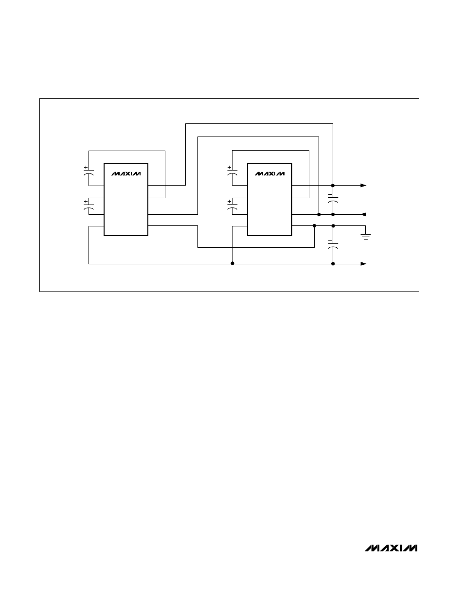
MAX680
22
µ
F
22
µ
F
C1-
8
7
6
5
C2+
V-
V+
1
2
3
4
C1+
V
CC
GND
C2-
MAX680
22
µ
F
22
µ
F
22
µ
F
V+ OUT
V- OUT
V
CC
IN
GND
22
µ
F
C1-
8
7
6
5
C2+
V-
V+
1
2
3
4
C1+
V
CC
GND
C2-
Figure 4. Paralleling MAX680s For Lower Source Resistance