Wire mode – Rainbow Electronics DS1821 User Manual
Page 3
DS1821
Page 3 of 17
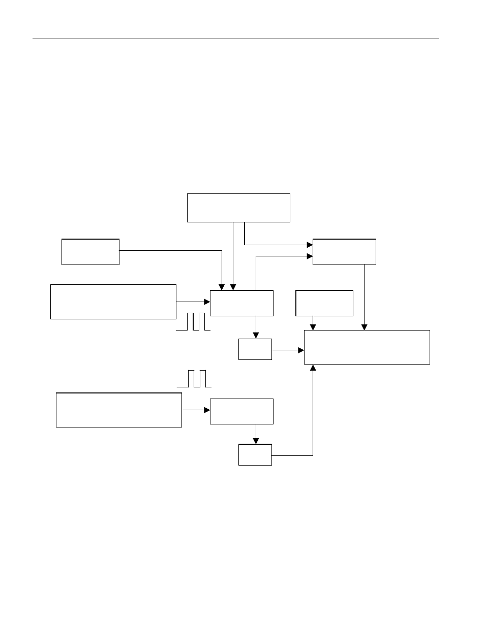
counter is preset with a base count that corresponds to –55
°
C. If the counter reaches 0 before the gate
period is over, the temperature register, which is preset to –55
°
C, is incremented by one degree, and the
counter is again preset with a starting value determined by the slope accumulator circuitry. The preset
counter value is unique for every temperature increment and compensates for the parabolic behavior of
the oscillators over temperature.
At this time, the counter is clocked again until it reaches 0. If the gate period is not over when the counter
reaches 0, the temperature register is incremented again. This process of presetting the counter, counting
down to zero, and incrementing the temperature register is repeated until the counter takes less time to
reach zero than the duration of the gate period of the high temp-co oscillator. When this iterative process
is complete, the value in the temperature register will indicate the centigrade temperature of the device.
TEMPERATURE MEASURING CIRCUITRY Figure 2
OPERATING MODES
The DS1821 has two operating modes: 1-wire mode and thermostat mode. The power-up operating mode
is determined by the user-programmable T/R
¯
bit in the status/configuration register: if T/R
¯
= 0 the device
powers-up in 1-wire mode, and if T/R
¯
= 1 the device powers-up in thermostat mode. The T/R
¯
bit is
stored in nonvolatile memory (EEPROM), so it will retain its value when the device is powered down.
1-WIRE MODE
The DS1821 arrives from the factory in 1-wire mode (T/R
¯
= 0). In this mode, the DQ pin of the DS1821
is configured as a 1-wire port for communication with a microprocessor using the protocols described in
SLOPE ACCUMULATOR
PRESET
COMPARE
LOW TEMPERATURE
COEFFICIENT OSCILLATOR
COUNTER
PRESET
=0
TEMPERATURE REGISTER
HIGH TEMPERATURE
COEFFICIENT OSCILLATOR
COUNTER
=0
INC
STOP
SET/CLEAR
LSB