Rainbow Electronics AT89LV51 User Manual
Features, Description, Pin configurations
4-45
Features
•
Compatible with MCS-51™ Products
•
4K Bytes of Reprogrammable Flash Memory
– Endurance: 1,000 Write/Erase Cycles
•
2.7V to 6V Operating Range
•
Fully Static Operation: 0 Hz to 12 MHz
•
Three-Level Program Memory Lock
•
128 x 8-Bit Internal RAM
•
32 Programmable I/O Lines
•
Two 16-Bit Timer/Counters
•
Six Interrupt Sources
•
Programmable Serial Channel
•
Low Power Idle and Power Down Modes
Description
The AT89LV51 is a low-voltage, high-performance CMOS 8-bit microcomputer with
4K bytes of Flash Programmable and Erasable Read Only Memory. The device is
manufactured using Atmel’s high density nonvolatile memory technology and is com-
patible with the industry standard MCS-51™ instruction set and pinout. The on-chip
Flash allows the program memory to be reprogrammed in-system or by a conven-
tional nonvolatile memory programmer. By combining a versatile 8-bit CPU with Flash
on a monolithic chip, the Atmel AT89LV51 is a powerful microcomputer which pro-
vides a highly flexible and cost effective solution to many embedded control applica-
tions. The AT89LV51 operates at 2.7 volts up to 6.0 volts.
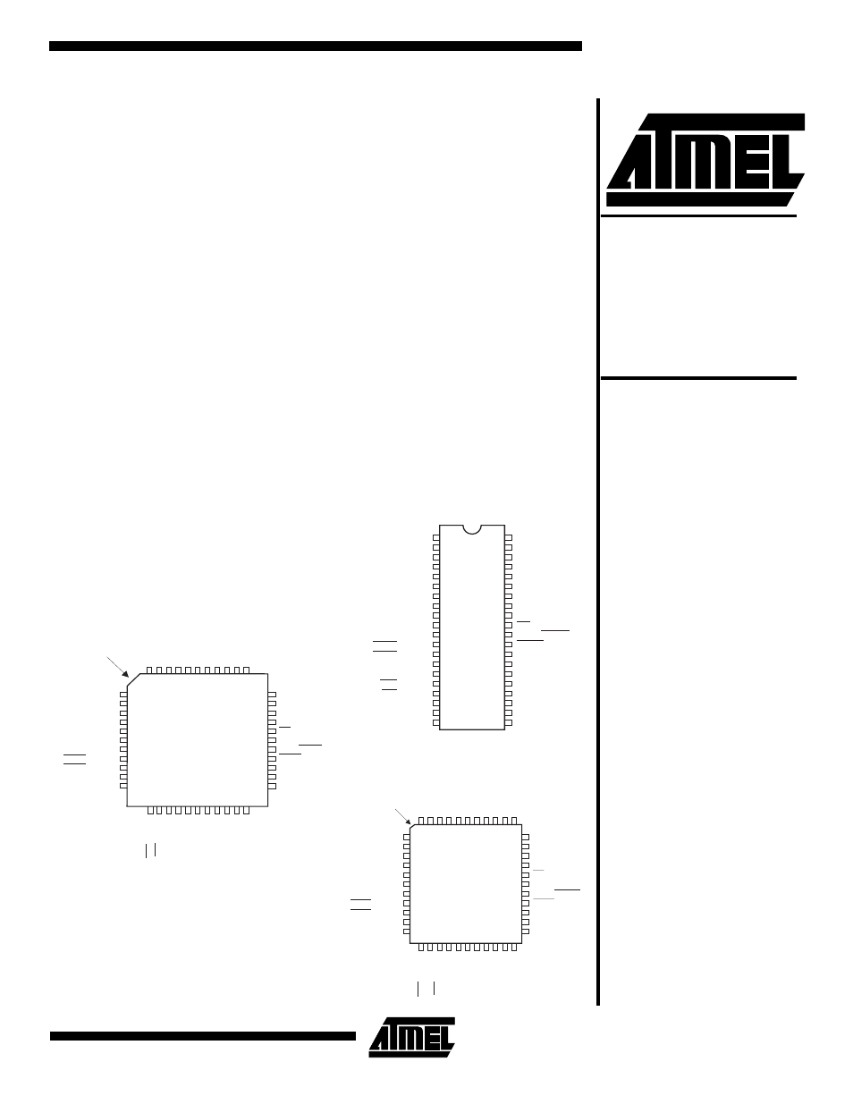
TQFP
2 3
1
I N D E X
C O R N E R
3 4
P1.0
VCC
P1.1
P1.2
P1.4
P1.3
NC
4 2
4 3
4 0
4 1
6
5
4
4 4
3
2
2 6
2 5
2 8
2 7
2 4
1 8
1 9
2 0
2 1
2 2
P 1 . 7
P 1 . 6
P 1 . 5
N C
7
8
9
1 0
1 1
1 2
1 3
1 4
1 5
1 6
1 7
2 9
3 0
3 9
3 8
3 7
3 6
3 5
3 3
3 2
3 1
N C
P S E N
XT
AL1
GND
XT
AL2
GND
P0.0
(AD0)
A L E / P R O G
()
P
3
.7
RD
E A / V P P
()
P
3
.6
WR
( R X D )
P 3 . 0
P 0 . 7
( A D 7 )
P 2 . 6
( A 1 4 )
P 0 . 6
( A D 6 )
P 0 . 5
( A D 5 )
P 0 . 4
( A D 4 )
P0.3
(AD3)
P0.2
(AD2)
P0.1
(AD1)
(
)
P 3 . 2
I N T 0
( T X D )
P 3 . 1
( T 1 )
P 3 . 5
(
)
P 3 . 3
I N T 1
( T 0 )
P 3 . 4
P 2 . 7
( A 1 5 )
(A11)
P2.3
(A12)
P2.4
(A10)
P2.2
(A
9)
P
2
.1
(A
8)
P
2
.0
R S T
P 2 . 5
( A 1 3 )
PDIP
P 1 . 0
V C C
P 1 . 1
P 0 . 0
( A D 0 )
P 1 . 2
(
)
P 3 . 2
I N T 0
A L E / P R O G
(
)
P 3 . 7
R D
P 2 . 3
( A 1 1 )
( T X D )
P 3 . 1
E A / V P P
(
)
P 3 . 6
W R
P 2 . 4
( A 1 2 )
( R X D )
P 3 . 0
P 0 . 7
( A D 7 )
( T 1 )
P 3 . 5
P 2 . 6
( A 1 4 )
R S T
P 0 . 6
( A D 6 )
P 1 . 7
P 0 . 5
( A D 5 )
P 1 . 6
P 0 . 4
( A D 4 )
P 1 . 5
P 0 . 3
( A D 3 )
P 1 . 4
P 0 . 2
( A D 2 )
P 1 . 3
P 0 . 1
( A D 1 )
(
)
P 3 . 3
I N T 1
P S E N
X TA L 2
P 2 . 2
( A 1 0 )
( T 0 )
P 3 . 4
P 2 . 7
( A 1 5 )
X TA L 1
P 2 . 1
( A 9 )
G N D
P 2 . 0
( A 8 )
P 2 . 5
( A 1 3 )
2 0
1 9
1 8
1 7
1 6
1 5
1
2
3
4
5
6
7
8
9
1 0
1 1
1 2
1 3
1 4
2 1
2 2
2 3
2 4
2 5
2 6
4 0
3 9
3 8
3 7
3 6
3 5
3 4
3 3
3 2
3 1
3 0
2 9
2 8
2 7
PLCC
P1.0
VCC
P1.1
P0.0
(AD0)
P1.2
A L E / P R O G
()
P
3
.
7
RD
XT
AL1
E A / V P P
()
P
3
.
6
WR
GND
( R X D )
P 3 . 0
P 0 . 7
( A D 7 )
P 2 . 6
( A 1 4 )
P 0 . 6
( A D 6 )
P 0 . 5
( A D 5 )
P 0 . 4
( A D 4 )
P0.3
(AD3)
P1.4
P0.2
(AD2)
P1.3
P0.1
(AD1)
P S E N
XT
AL2
(
)
P 3 . 2
I N T 0
( T X D )
P 3 . 1
( T 1 )
P 3 . 5
(
)
P 3 . 3
I N T 1
( T 0 )
P 3 . 4
P 2 . 7
( A 1 5 )
(A11)
P2.3
(A12)
P2.4
(A10)
P2.2
(A
9)
P
2
.1
(A
8)
P
2
.0
NC
2 3
1
R S T
P 1 . 7
P 1 . 6
P 1 . 5
I N D E X
C O R N E R
N C
NC
P 2 . 5
( A 1 3 )
3 4
N C
4 2
4 3
4 0
4 1
6
5
4
4 4
3
2
2 6
2 5
2 8
2 7
1 8
1 9
2 0
2 4
2 1
2 2
7
8
9
1 0
1 1
1 2
1 3
1 4
1 5
1 6
1 7
2 9
3 0
3 9
3 8
3 7
3 6
3 5
3 3
3 2
3 1
8-Bit
Microcontroller
with 4K Bytes
Flash
AT89LV51
Pin Configurations
0303D-D–12/97
(continued)