Rainbow Electronics BA4908 User Manual
Page 2
I
ST
-
5.30
0.55
5.60
0.80
5.90
mA
V
V
V
O
1
I
O
1=80mA
I
O
2=120mA
V
O
2
≥
8.25V
I
O
2=120mA
I
O
3=400mA
V
O
3
≥
11.7V
STAN BY pin = 0V
8.25
8.70
9.15
V
O
2
-
150
0.4
300
0.7
-
mA
∆
V
O
23
I
O
2
V
V
O
5
≥
5.3V
I
O
5=120mA
-
150
0.4
300
0.7
-
mA
∆
V
O
53
I
O
5
V
V
O
1
≥
5.3V
I
O
1=80mA
-
100
0.3
200
0.7
-
mA
∆
V
O
13
I
O
1
V
V
-
1.0
1.5
∆
V
O
31
500
900
-
mA
I
O
3
I
O
4=400mA
V
O
4
≥
11.7V
V
-
1.0
1.5
∆
V
O
41
V
O
5
500
900
-
mA
I
O
4
I
O
5=50mA
V
5.3
5.6
5.9
Electrical characteristics (
Unless otherwise noted: Ta=25˚C, Vcc=13.2V)
V
O
6
≥
8.25V
I
O
6=200mA
-
250
0.4
500
0.7
-
mA
∆
V
O
63
I
O
6
V
V
O
6
I
O
6=140mA
V
8.25
8.70
9.15
Symbol
Min.
Max.
Unit
Conditions
Typ.
Parameter
Circuit current at standby
Output voltage(VDD)1
Minimum I/O voltage difference
Output current capacity
Output voltage(COM)2
Minimum I/O voltage difference
Output current capacity
Minimum I/O voltage difference
Output voltage(TUNER5.6)5
Output current capacity
Minimum I/O voltage difference
Output voltage(TUNER8.7)6
Output current capacity
I/O voltage difference
(AMP)3
Output current capacity
I/O voltage difference
(ANT)4
Output current capacity
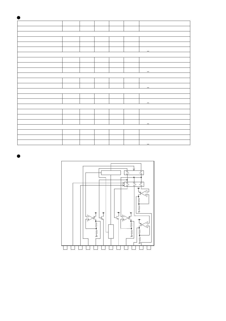
Block Diagram
N.C. TUNER
8.7
ANT SW
TUNER
5.6
SW
STB
V
DD
5.6V
AMP
Vcc
ANT
COM
8.7V
TUNER
5.6
TUNER
8.7
GND
Regulator
12
1
2
3
4
5
6
7
8
9
10
11
BA4908
O
ve
r v
olta
ge
pro
tec
tio
n
∗
This product is not designed for protection against radioactive rays.
∗
Output current capacity must be set below MINIMUM of the specification.