Regulator ics ba3963 – Rainbow Electronics BA3963 User Manual
Page 8
214
Regulator ICs
BA3963
(4)
Overcurrent protection circuit
An overcurrent protection circuit is installed in each out-
put system, based on the respective output current. This
prevents IC destruction by overcurrent, by limiting the
current with a curve shape of “7” in the voltage-current
graph. The IC is designed with margins so that current
flow will be restricted and latching will be prevented even
if a large current suddenly flows through a large capaci-
tor. Note that these protection circuits are only good for
preventing damage from sudden accidents. Make sure
your design does not cause the protection circuit to oper-
ate continuously under transitional conditions (for
instance, when output is clamped at 1V
F
or higher, short
mode circuit operates at 1V
F
or lower). Note that the cir-
cuit ability is negatively correlated with temperature.
(5)
Thermal protection circuit
A built-in thermal protection circuit prevents thermal
damage to the IC. All outputs are switched OFF when the
circuit operates, and revert to the original state when
temperature drops to a certain level.
(6)
Grounding
To minimize the variation of output voltage due to varia-
tions in load current, the GND (pin 12, for large current)
and the PRE GND (pin 11, for small current) pins are sep-
arately provided. Make sure to connect circuits to correct
pins.
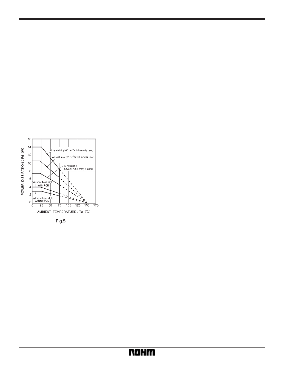
F
Thermal derating curve
Estimate of allowable power dissipation (P
MAX.
)
S
Power consumed by OUT 5V
P
1
= (V
CC
*
5V)
maximum output current of OUT 5V
S
Power consumed by OUT 7V
P
2
= (V
CC
*
7V)
maximum output current of OUT 7V
S
Power consumed by the reset output
P
3
= (V
CC
*
4.95V)
maximum output current of the reset output
S
Power consumed internally by each circuit
P
4
= V
CC
supply current
P
MAX.
= P
1
)
P
2
)
P
3
)
P
4