Configuration register figure 4, Resolution configuration table 4, Start, stop, and ack signals figure 5 – Rainbow Electronics DS1631 User Manual
Page 5
DS1631
5 of 14
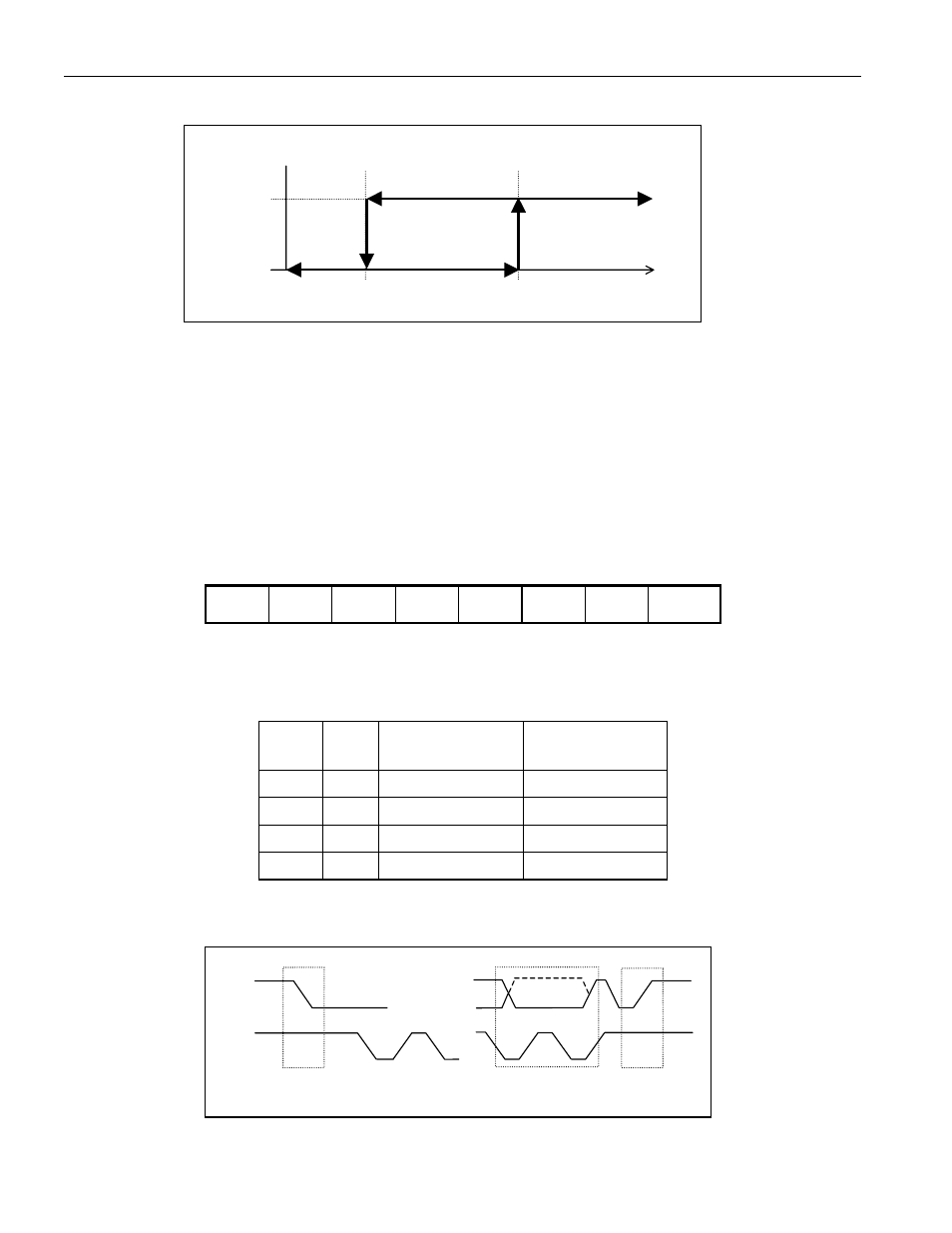
THERMOSTAT OUTPUT OPERATION
Figure 3
CONFIGURATION REGISTER
The configuration register allows the user to program various DS1631 options such as conversion
resolution, T
OUT
polarity, and operating mode. It also provides information to the user about conversion
status, EEPROM activity, and thermostat activity. The configuration register is arranged as shown in
Figure 4 and detailed descriptions of each bit are provided in Table 5. This register can be read from and
written to using the Access Config command. Note that the POL and 1SHOT bits are stored in EEPROM
and all other configuration register bits are SRAM.
CONFIGURATION REGISTER Figure 4
MSb
bit 6
bit 5
bit 4
bit 3
bit 2
bit 1
LSb
DONE
THF
TLF
NVB
R1
R0
POL* 1SHOT*
*NV (EEPROM)
RESOLUTION CONFIGURATION Table 4
R1
R0
RESOLUTION CONVERSION
TIME (MAX)
0
0
9-bit
93.75ms
0
1
10-bit
187.5ms
1
0
11-bit
375ms
1
1
12-bit
750ms
START, STOP, AND ACK SIGNALS Figure 5
T
L
T
H
Temp
POL=1 (T
OUT
is active high)
Logic 0
Logic 1
T
OUT
SCL
SDA
START
Condition
STOP
Condition
…
…
ACK (or NACK)
From Receiver