Rainbow Electronics АТ89С2051 User Manual
Pin configuration, Features, Description
1
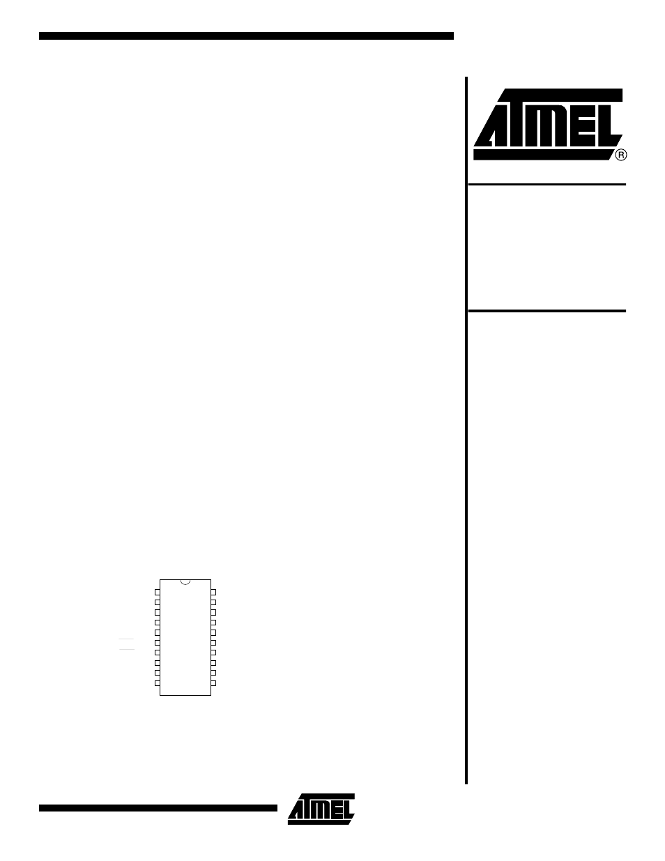
Pin Configuration
PDIP/SOIC
1
2
3
4
5
6
7
8
9
10
20
19
18
17
16
15
14
13
12
11
RST/VPP
(RXD) P3.0
(TXD) P3.1
XTAL2
XTAL1
(INT0) P3.2
(INT1) P3.3
(TO) P3.4
(T1) P3.5
GND
VCC
P1.7
P1.6
P1.5
P1.4
P1.3
P1.2
P1.1 (AIN1)
P1.0 (AIN0)
P3.7
Features
•
Compatible with MCS-51
™
Products
•
2K Bytes of Reprogrammable Flash Memory
– Endurance: 1,000 Write/Erase Cycles
•
2.7V to 6V Operating Range
•
Fully Static Operation: 0 Hz to 24 MHz
•
Two-level Program Memory Lock
•
128 x 8-bit Internal RAM
•
15 Programmable I/O Lines
•
Two 16-bit Timer/Counters
•
Six Interrupt Sources
•
Programmable Serial UART Channel
•
Direct LED Drive Outputs
•
On-chip Analog Comparator
•
Low-power Idle and Power-down Modes
Description
The AT89C2051 is a low-voltage, high-performance CMOS 8-bit microcomputer with
2K bytes of Flash programmable and erasable read only memory (PEROM). The
device is manufactured using Atmel’s high-density nonvolatile memory technology
and is compatible with the industry-standard MCS-51 instruction set. By combining a
versatile 8-bit CPU with Flash on a monolithic chip, the Atmel AT89C2051 is a power-
ful microcomputer which provides a highly-flexible and cost-effective solution to many
embedded control applications.
The AT89C2051 provides the following standard features: 2K bytes of Flash, 128
bytes of RAM, 15 I/O lines, two 16-bit timer/counters, a five vector two-level interrupt
architecture, a full duplex serial port, a precision analog comparator, on-chip oscillator
and clock circuitry. In addition, the AT89C2051 is designed with static logic for opera-
tion down to zero frequency and supports two software selectable power saving
modes. The Idle Mode stops the CPU while allowing the RAM, timer/counters, serial
port and interrupt system to continue functioning. The power-down mode saves the
RAM contents but freezes the oscillator disabling all other chip functions until the next
hardware reset.
Rev. 0368E–02/00
8-bit
Microcontroller
with 2K Bytes
Flash
AT89C2051
Document Outline
- Pin Configuration
- Features
- Description
- Block Diagram
- Pin Description
- Oscillator Characteristics
- Special Function Registers
- Restrictions on Certain Instructions
- Program Memory Lock Bits
- Lock Bit Protection Modes(1)
- Idle Mode
- Power-down Mode
- Programming The Flash
- Programming Interface
- Flash Programming Modes
- Flash Programming and Verification Characteristics
- Flash Programming and Verification Waveforms
- Absolute Maximum Ratings*
- DC Characteristics
- External Clock Drive Waveforms
- External Clock Drive
- Serial Port Timing: Shift Register Mode Test Conditions
- Shift Register Mode Timing Waveforms
- AC Testing Input/Output Waveforms(1)
- Float Waveforms(1)
- Ordering Information