Rainbow Electronics BA6161N_F User Manual
Page 3
263
Regulator ICs
BA6161N / BA6161F
F
Circuit operation
A zener diode on the feedback pin provides reference
voltage and compensates for temperature changes.
Feedback current is fed from the zener diode to the oscil-
lator.
Blocking oscillation is provided by connecting the exter-
nal coil L between the oscillator drive pin and the V
IN
pin.
The potential at the oscillator drive pin can be raised by
using this oscillation. The output voltage is constant be-
cause the feedback current is always supplied to the os-
cillation circuit.
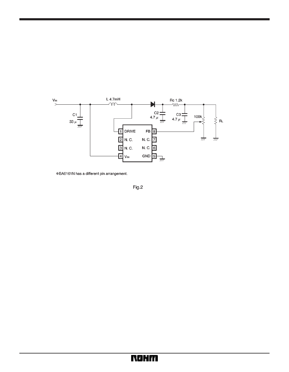
F
Application example
F
Operation notes
(1)
When an output voltage greater than the reference
output voltage (33.3V) is required, use a variable resistor
(Murata RVG6P02-104M or equivalent product) with
good temperature characteristics as shown in the ap-
plication circuit. Make sure, however, that the voltage of
the oscillator drive pin does not exceed 42V.
(2)
The coil to be connected between pins 2 and 3
should have the lowest possible DC resistance (under
10
Ω
) and an inductance of 4.7mH (Sumida Electronics
RC095-472K or equivalent product).