Rainbow Electronics BA33C25FP_HFP User Manual
Page 2
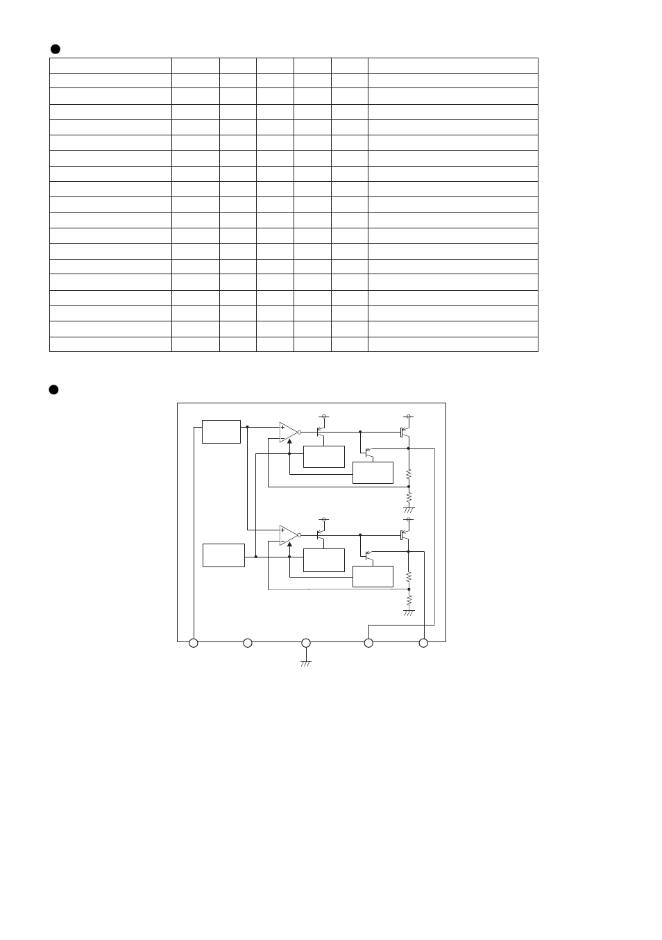
Block Diagram
Electrical characteristics (
Unless otherwise noted; Ta=25˚C, Vcc=5V)
∗
2
∗
2
Parameter
Symbol
Min.
Typ.
Max.
Unit
Conditions
Io=0mA, Io2=0mA
Io1=500mA
Io1=500mA, Vcc=3.135V
f=120Hz, ein=1Vrms, Io1=200mA
Vcc=4.1 → 16V, Io1=500mA
Io1=0mA → 1A
Io1=5mA, Tj=0~125
˚C
Vcc=16V
Io2=500mA
f=120Hz, ein=1Vrms, Io2=200mA
Vcc=4.1 → 16V, Io2=500mA
Io2=0mA → 1A
Io1=5mA, Tj=0~125
˚C
Vcc=16V
Ib
Vo1
∆
Vd1
Io1
R.R. 1
Reg.I1
Reg.L1
Tcvo1
I
OS
1
Vo2
Io2
R.R. 2
Reg.I2
Reg.L2
Tcvo2
I
OS
2
-
3.234
-
1.0
50
-
-
-
-
2.450
1.0
50
-
-
-
-
0.8
3.3
0.25
-
58
5
30
±
0.01
300
2.5
-
58
5
30
±
0.01
270
1.5
3.366
0.50
-
-
30
75
-
-
2.550
-
-
30
75
-
-
mA
V
V
A
dB
mV
mV
% /˚C
mA
V
A
dB
mV
mV
% / ˚C
mA
Bias current
<3.3V output>
Output voltage 1
Min. I/O voltage difference 1
Output current capacity 1
Ripple rejection 1
Input stability 1
Load stability 1
Output voltage temperature
coefficient 1
Output short current 1
<2.5V output>
Output voltage 2
Output current capacity 2
Ripple rejection 2
Input stability 2
Load stability 2
Output voltage temperature
coefficient 2
Output short current 2
∗
This product is not designed for protection against radioactive rays.
∗
2 Design guaranteed (All total inspection is not performed.)
Reference
Voltage
Sat.
Prevention
Current
Limit
Current
Limit
Sat.
Prevention
Thermal
Shut Down
Vcc
Vcc
Vcc
Vcc
Vcc
Vo2
GND(FIN) Vo1
N.C.
BA33C25FP/HFP