Regulator ics, Internal circuit configuration diagram – Rainbow Electronics BA178MххT_FP User Manual
Page 2
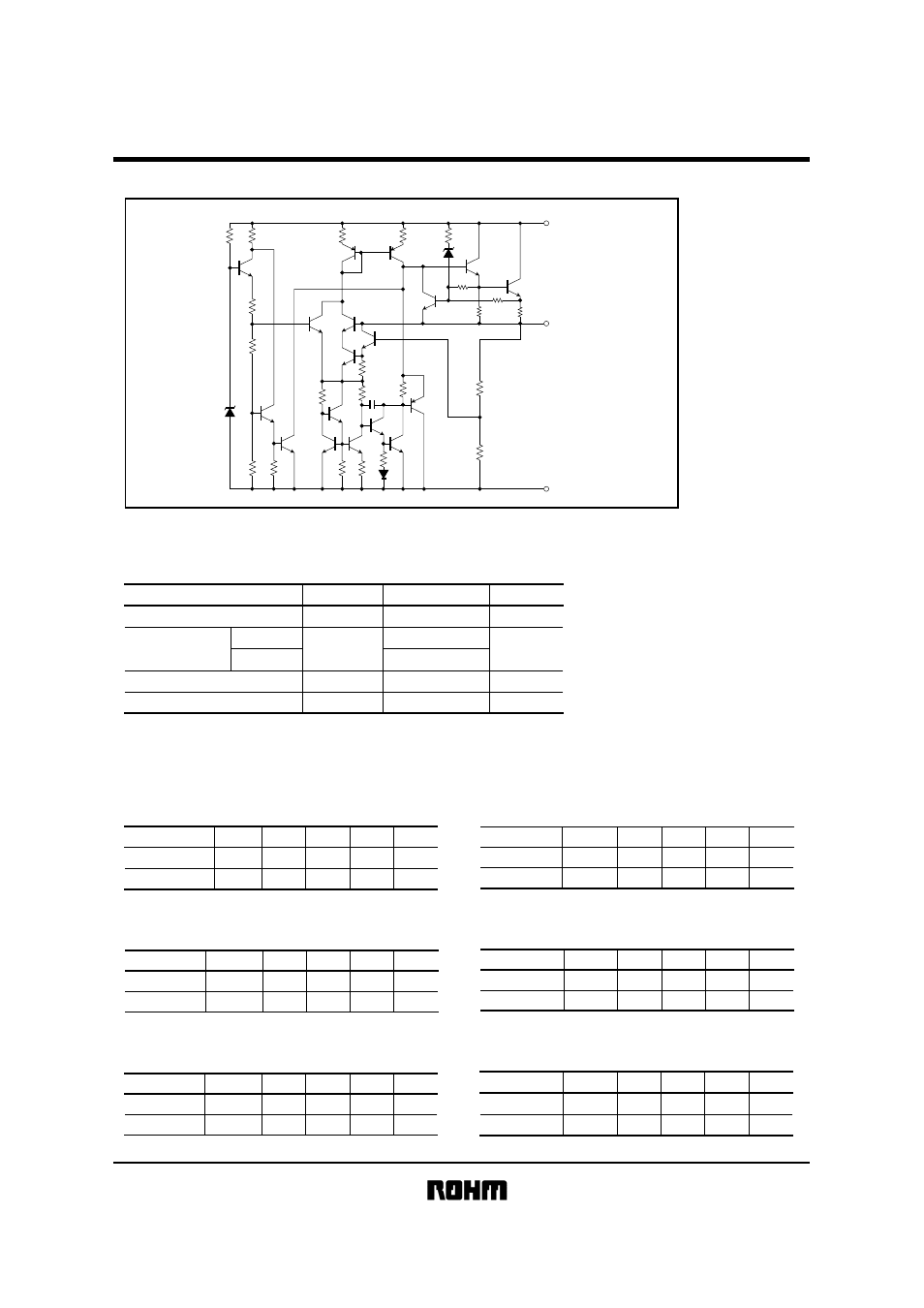
BA178M!!T / BA178M!!FP series
Regulator ICs
"
"
"
"
Internal circuit configuration diagram
R
4
R
2
R
16
R
15
C
1
R
10
R
8
R
9
R
11
R
12
R
20
R
19
R
21
R
17
R
13
D
2
R
5
R
6
R
1
R
7
R
22
R
10
R
3
R
14
D
3
D
1
Q
3
Q
11
Q
4
Q
2
Q
7
Q
5
Q
13
Q
12
Q
10
Q
6
Q
8
Q
9
Q
15
Q
16
Q
17
Q
1
Q
14
Q
18
(2)
COMMON
(3)
OUTPUT
(1)
INPUT
"
"
"
"
Absolute maximum ratings (Ta=25
°C)
^Common specifications for BA178M!!T / FP seriesp
Parameter
Symbol
Limits
Unit
Applied voltage
V
IN
35
V
Power dissipation
W
Operating temperature
Topr
°
C
Storage temperature
Tstg
°
C
2.0
∗
1.0
∗
−
40
~
+
85
−
55
~
+
150
Pd
TO220FP
TO252
−
3
∗
Reduced by 16 mW (TO220FP) and 8 mW (TO252-3) for each increase in Ta of 1
°
C
over 25
°
C
(without heat sink).
"
"
"
"
Recommended operating conditions (Ta=25
°C)
BA178M05T / FP
Parameter
Symbol
Min.
Typ.
Max.
Unit
Input voltage
7.5
−
−
V
−
0.5
A
Output current
20
V
IN
I
O
BA178M07T / FP
Parameter
Symbol
Min.
Typ.
Max.
Unit
9.5
−
22
V
−
−
0.5
A
V
IN
I
O
Input voltage
Output current
BA178M09T / FP
Parameter
Symbol
Min.
Typ.
Max.
Unit
11.5
−
V
−
−
0.5
A
24
V
IN
I
O
Input voltage
Output current
BA178M06T / FP
Parameter
Symbol
Min.
Typ.
Max.
Unit
8.5
−
21
V
−
−
0.5
A
V
IN
I
O
Input voltage
Output current
BA178M08T / FP
Parameter
Symbol
Min.
Typ.
Max.
Unit
10.5
−
23
V
−
−
0.5
A
V
IN
I
O
Input voltage
Output current
BA178M10T / FP
Parameter
Symbol
Min.
Typ.
Max.
Unit
12.5
−
25
V
−
−
0.5
A
V
IN
I
O
Input voltage
Output current