Figure 5. differential drive circuit of, Figure 5, Figure 4 – Rainbow Electronics ADC12040 User Manual
Page 16: Applications information
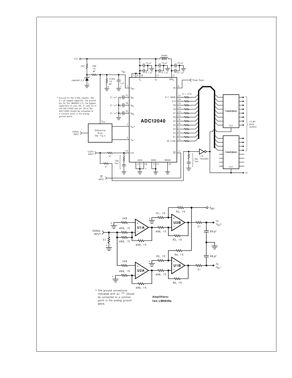
Applications Information
(Continued)
ing buffers between the ADC outputs and any other circuitry
(74ACQ541, for example). Only one input should be con-
nected to each output pin. Additionally, inserting series re-
sistors of 47
Ω to 100Ω at the digital outputs, close to the
ADC pins, will isolate the outputs from trace and other circuit
capacitances and limit the output currents, which could oth-
erwise result in performance degradation. See Figure 4.
20014813
FIGURE 4. Simple Application Circuit with Single-Ended to Differential Buffer
20014814
FIGURE 5. Differential Drive Circuit of Figure 4
ADC12040
www.national.com
16
See also other documents in the category Rainbow Electronics Sensors:
- MAX5151 (16 pages)
- MAXQ3108 (64 pages)
- MAX5661 (39 pages)
- MAX6691 (7 pages)
- MAX5362 (12 pages)
- ADC10158 (26 pages)
- MAX8922L (14 pages)
- MAX8596Z (8 pages)
- MAX7491 (18 pages)
- MAX15040 (15 pages)
- MAX5177 (16 pages)
- ADC08138 (22 pages)
- MAX5961 (42 pages)
- T89C51RD2 (86 pages)
- MAX16055 (9 pages)
- MAX6659 (17 pages)
- ADC0820 (20 pages)
- MAX6678 (19 pages)
- MAX8884Z (15 pages)
- MAX16915 (9 pages)
- MAX8620 (18 pages)
- MAX5144 (12 pages)
- MAX6670 (8 pages)
- MAX8760 (39 pages)
- W78C32C (14 pages)
- MX7533 (8 pages)
- MAX8727 (13 pages)
- MAX9053 (15 pages)
- W78C54 (16 pages)
- MAX8614B (15 pages)
- W90N740 (219 pages)
- MAX6626 (13 pages)
- ADC10738 (30 pages)
- MAX17000 (31 pages)
- MAX5051 (21 pages)
- MAXQ1004 (18 pages)
- MAX6871 (51 pages)
- MX7847 (12 pages)
- MAX6608 (6 pages)
- MAX17083 (15 pages)
- MAX6641 (17 pages)
- MAX5251 (16 pages)
- MAX6338 (8 pages)
- MAX6690 (16 pages)
- MAX8668 (18 pages)