Status register, Figure 15. status register format – Rainbow Electronics DS2756 User Manual
Page 17
DS2756: High-Accuracy Battery Fuel Gauge with Programmable Suspend Mode
17 of 26
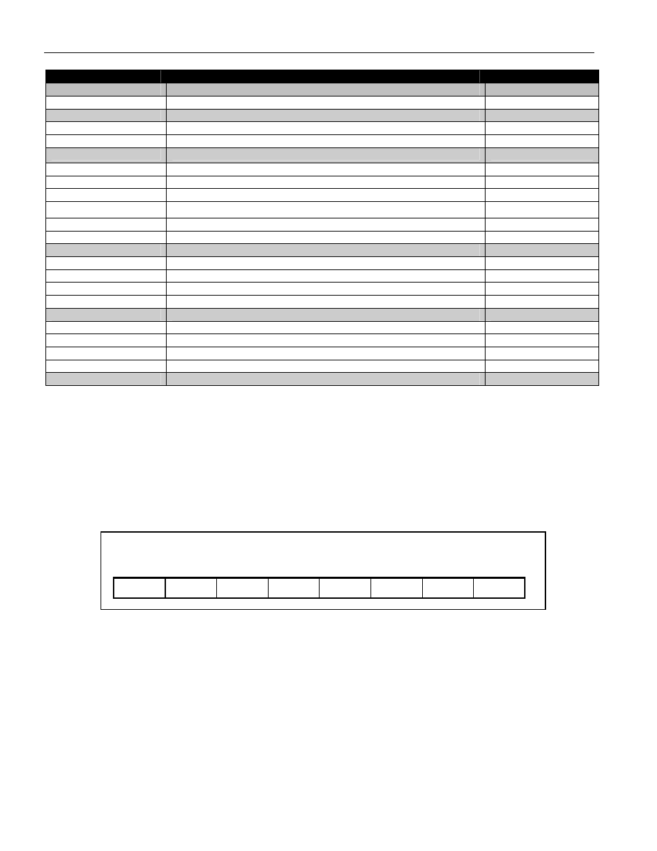
Table 2. Memory Map
ADDRESS (HEX)
DESCRIPTION
READ/WRITE
00
Reserved
01 Status
Register
R
02 to 06
Reserved
07 EEPROM
Register
R/W
08
Special Feature Register
R/W
09 to 0B
Reserved
0C Voltage
Register
MSB
R
0D Voltage
Register
LSB
R
0E
Current Register MSB
R
0F
Current Register LSB
R
10
Accumulated Current Register MSB
R/W
11
Accumulated Current Register LSB
R/W
12 to 17
Reserved
18
Temperature Register MSB
R
19
Temperature Register LSB
R
1A
Average Current Register MSB
R
1B
Average Current Register LSB
R
1C to 1F
Reserved
20 to 3F
EEPROM, block 0
R/W*
40 to 5F
EEPROM, block 1
R/W*
60 to 7F
EEPROM, block 2
R/W*
80 to 8F
SRAM
R/W
90 to FF
Reserved
*Each EEPROM block is read/write until locked by the LOCK command, after which it is read-only.
STATUS REGISTER
The default values for the Status Register bits are stored in lockable EEPROM in the corresponding bits of address
31h. A Recall Data command for EEPROM block 1 recalls the default values into the Status Register bits. The
format of the Status Register is shown in Figure 15. The function of each bit is described in detail in the following
paragraphs. Note that all bits are Read Only.
Figure 15. STATUS REGISTER FORMAT
Address 01h
bit 7
bit 6
bit 5
bit 4
bit 3
bit 2
bit 1
bit 0
PIE1 PIE0 PMOD
RNAOP
UVEN IOS OBEN OVD
PIE1, PIE0—Programmable Suspend Interrupt Enable. A non zero value in these bits enables the DS2756 to enter
Suspend mode, and sets the Suspend Period (t
SUS
) for the low power oscillator timeout. A value of 00b disables the
DS2756 from entering Suspend mode and allows the DS2756 to enter Sleep mode.