Wire bus system – Rainbow Electronics DS1920 User Manual
Page 8
DS1920
8 of 22
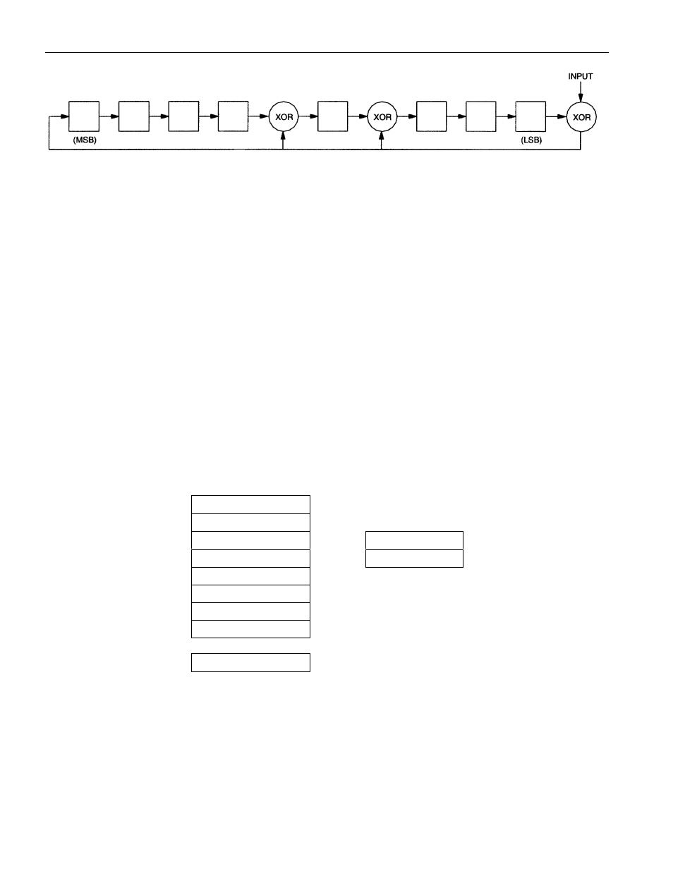
1-WIRE CRC CODE Figure 6
MEMORY
The DS1920’s memory is organized as shown in Figure 7. The memory consists of a scratchpad and 2
bytes of EEPROM which store the high and low temperature triggers TH and TL. The scratchpad helps
insure data integrity when communicating over the 1-Wire bus. Data is first written to the scratchpad
where it can be read back. After the data has been verified, a copy scratchpad command will transfer the
data to the EEPROM. This process insures data integrity when modifying the memory.
The scratchpad is organized as 8 bytes of memory. The first 2 bytes contain the measured temperature
information. The 3
rd
and 4
th
bytes are volatile copies of TH and TL and are refreshed with every power-on
reset. The next 2 bytes are not used; upon reading back, however, they will appear as all logic 1s. The 7
th
and 8
th
bytes are count registers, which may be used in obtaining higher temperature resolution (see
“Operation-Measuring Temperature” section).
There is a 9
th
byte which may be read with a Read Scratchpad command. This byte is a cyclic redundancy
check (CRC) over all of the 8 previous bytes. This CRC is implemented as described in the section titled
“CRC Generation.”
DS1920 MEMORY MAP Figure 7
SCRATCHPAD
BYTE
EEPROM
TEMPERATURE LSB
0
TEMPERATURE MSB
1
TH/USER BYTE 1
2
TH/USER BYTE 1
TL/USER BYTE 2
3
TL/USER BYTE 2
RESERVED
4
RESERVED
5
COUNT REMAIN
6
COUNT PER °C
7
CRC
8
1-WIRE BUS SYSTEM
The 1-Wire bus is a system which has a single bus master and one or more slaves. The DS1920 behaves
as a slave. The discussion of this bus system is broken down into three topics: hardware configuration,
transaction sequence, and 1-Wire signaling (signal types and timing).