Api4000m, Integrated, Series – Rainbow Electronics API4000M User Manual
Page 9: Circuits inc. voice otp module
INTEGRATED
API4000M
SERIES
CIRCUITS INC. VOICE OTP MODULE
9
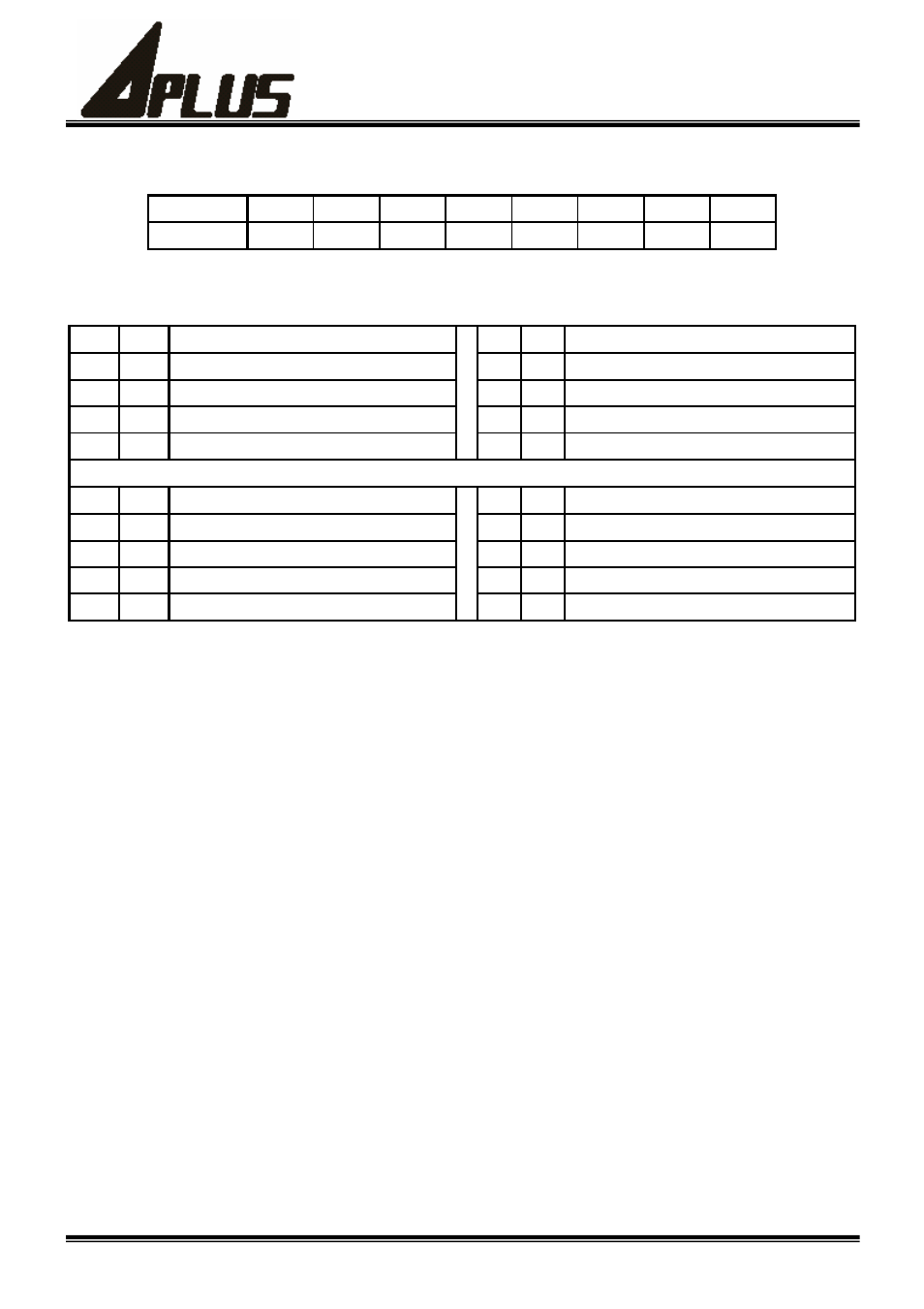
(2) PB ﹕Output Data Port B consists of Output Pin PI2 ~ PI0, each pin of PB has following act.
PB
bit7 bit6 bit5 bit4 bit3 bit2 bit1 bit0
Output
Pin
- - - - - PI2
PI1
PI0
PS ﹕If PI2 ~ PI0 are set to Input Pin, bit2 ~ bit0 will not affect PI2 ~ PI0 of state.
(3) PC ﹕Output Data Port C can set Each Pin’s act of PIO3 ~ PIO0, Following is their correspondent.
bit7 bit6
PIO3
bit5 bit4
PIO2
0
0
Pull-low Input Pin, no input trigger.
0
0
Pull-low Input Pin, no input trigger.
0
1
Pull-low Input Pin, with input trigger.
0
1
Pull-low Input Pin, with input trigger.
1
0
Floating Input Pin, no input trigger.
1
0
Floating Input Pin, no input trigger.
1
1
Output Pin.
1
1
Output Pin.
Bit3 bit2
PIO1
bit1 bit0
PIO0
0
0
Pull-low Input Pin, no input trigger.
0
0
Pull-low Input Pin, no input trigger.
0
1
Pull-low Input Pin, with input trigger.
0
1
Pull-low Input Pin, with input trigger.
1
0
Floating Input Pin, no input trigger.
1
0
Floating Input Pin, no input trigger.
1
1
Output Pin.
1
1
Output Pin.
PS ﹕Each bit of PC after API4000M power on, initial state is 0.
(4) PD ﹕Output Data Port D can choice Data Bank, set Operate Voltage, set each pin of PO3 ~ PO0 and PI3 ~ PI0
function, following is their correspondent.
(a) bit7 not use, bit6 must set to 0.
(b) bit5 = 0, Operate Voltage is 4.5V﹔bit5 =1, Operate Voltage is 3.0V.
(c) bit4 = 0, disable PO3 ~ PO0 each Pin’s output﹔bit4 = 1, enable PO3 ~ PO0 each Pin’s output.
(d) bit3 = 0, set PI2 ~ PI0 to Input Pin ﹔bit3 = 1, set PI2 ~ PI0 to Output Pin.
(e) bit2 = 0 set PI3 to Pull-low Input Pin ﹔bit2 = 1 set PI3 to Floating Input Pin.
(f) bit1 = 0 set PI2 ~ PI0 to Pull-low Pin ﹔bit1 = 1 set PI2 ~ PI0 to Floating Pin.
(g) bit0 = 0 set Data Bank to group A of 16 registers ﹔bit0 = 1 set Data Bank to group B of 16 registers.
(h) Each bit of PD after API4000M power on, initial state is 0.
(5) PE ﹕Output Data Port E can set Sound and Melody’s operate mode, the following is description.
(a) bit7 must set 0.
(b) bit6 = 0, Sound Processor Off ﹔bit6 = 1, Sound Processor On.
(c) bit5 = 0, Melody Off ﹔bit5 = 1, Melody Start and On.
(d) bit4 = 0,no action ﹔bit4 = 1,Off Melody Channels.
(e) bit3 = 0, CH4 is Sound Mode ﹔bit3 = 1, CH4 is Melody Mode.
(f) bit2 = 0, CH3 is Sound Mode ﹔bit2 = 1, CH3 is Melody Mode.
(g) bit1 = 0, CH2 is Sound Mode ﹔bit1 = 1, CH2 is Melody Mode.
(h) bit0 = 0, CH1 is Sound Mode ﹔bit0 = 1, CH1 is Melody Mode.
(i) After API4000M shut down, Each bit of PE will reset to 0.