Detailed description – Rainbow Electronics MAX6781 User Manual
Page 6
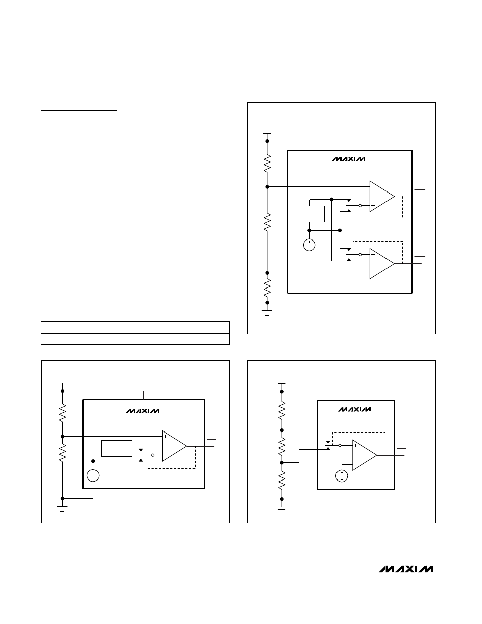
MAX6775–MAX6781
Detailed Description
These battery monitors have an active-low output that
asserts when the input falls below a set voltage. They
also offer hysteresis for noise immunity, and to remove
the possibility of output chatter due to battery terminal
voltage recovery after load removal. They are available
with one or two monitors per package, with push-pull or
open-drain outputs, and with internally set or externally
adjustable hysteresis (dual-channel devices offer only
internally fixed hysteresis). Figures 1, 2, and 3 show
block diagrams and typical connections. See the
Selector Guide for details.
Low-Battery Output
All devices are offered with either push-pull or open-
drain outputs (see the Selector Guide). The MAX6781
has one push-pull output and one open-drain output,
configured as in Table 1.
On all devices with open-drain outputs an external
pullup resistor is required. The open-drain pullup resis-
tor can connect to an external voltage up to +6V,
regardless of the voltage at BATT.
Low-Power, 1%-Accurate Battery
Monitor in µDFN and SC70 Packages
6
_______________________________________________________________________________________
Table 1. MAX6781 Outputs
DEVICE
LBO1
LBO2
MAX6781
Push-Pull
Open-Drain
LBI1
LBO1
0
1
BATT
GND
V
REF
V
BATT
LBI2
LBO2
0
1
MAX6779
MAX6780
MAX6781
HYSTERESIS
CONTROL
Figure 2. Dual-Channel Fixed-Hysteresis Block Diagram
LBI
LBO
0
1
BATT
GND
R
L
V
REF
V
BATT
R
H
MAX6775
MAX6776
HYSTERESIS
CONTROL
Figure 1. Single-Channel Fixed-Hysteresis Block Diagram
LBL
LBO
0
1
LBH
BATT
GND
R
HYST
V
REF
V
BATT
R
H
R
L
MAX6777
MAX6778
Figure 3. Single-Channel Adjustable-Hysteresis Block Diagram