Pin description (continued) – Rainbow Electronics MAX8903A User Manual
Page 10
MAX8903A
2A 1-Cell Li+ DC-DC Charger for USB*
and Adapter Power
10
______________________________________________________________________________________
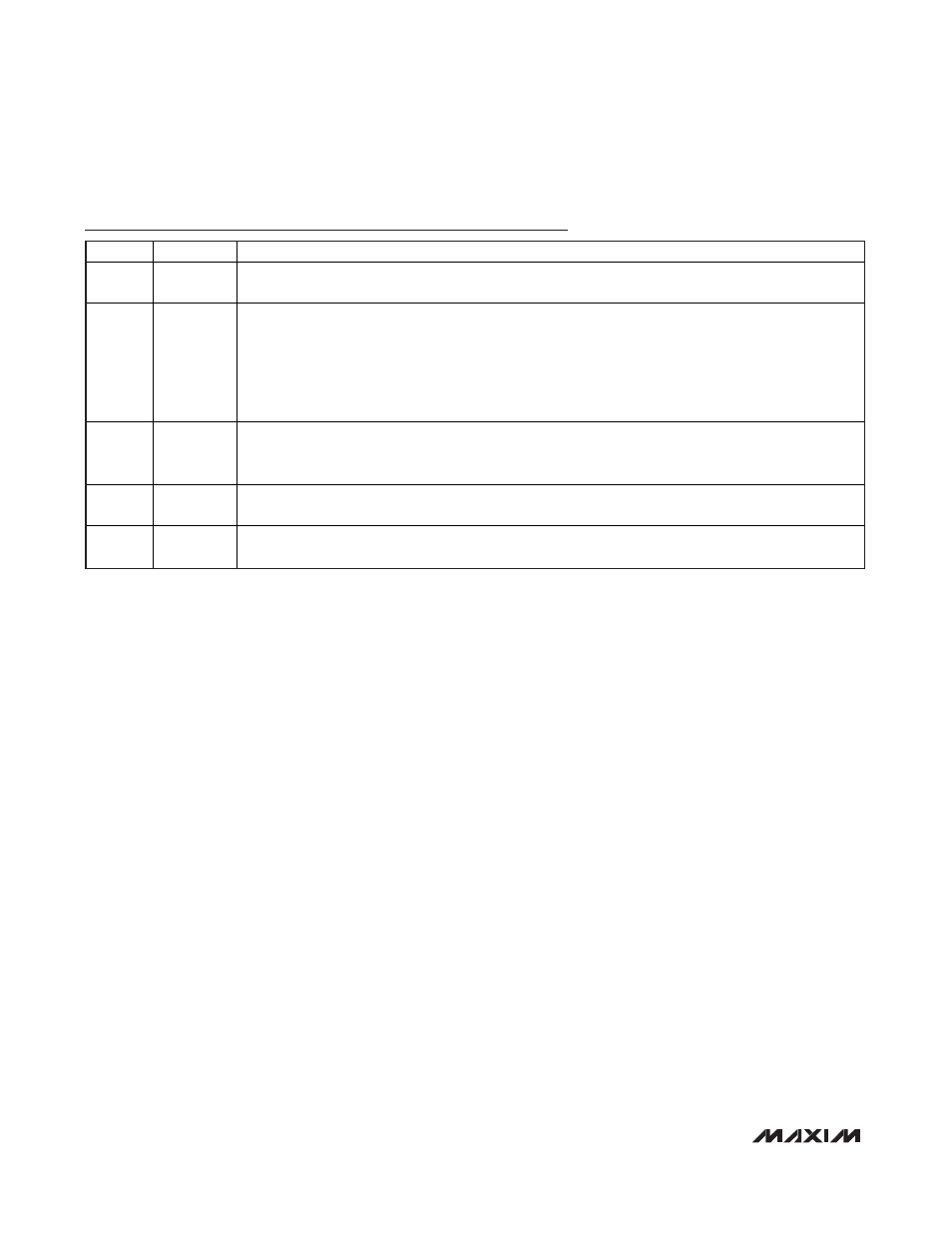
Pin Description (continued)
PIN
NAME
FUNCTION
22
CHG
Charger Status Output. Active-low, open-drain output pulls low when the battery is in fast-charge or
prequal. Otherwise, CHG is high impedance.
23, 24
SYS
System Supply Output. SYS connects to BAT through an internal 50m
Ω system load switch when DC or
USB are invalid, or when the SYS load is greater than the input current limit.
When a valid voltage is present at DC or USB, SYS is limited to 4.4V. When the system load (I
SYS
)
exceeds the DC or USB current limit, SYS is regulated to 50mV below BAT, and both the powered input
and the battery service SYS.
Bypass SYS to GND with a 10µF X5R or X7R ceramic capacitor. Both SYS pins must be connected
together externally.
25, 26
CS
70m
Ω Current-Sense Input. Connect the step-down inductor from LX to CS. When the step-down
regulator is on, there is a 70m
Ω current-sense MOSFET from CS to SYS. When the step-down regulator is
off, the internal CS MOSFET turns off to block current from SYS back to DC.
27, 28
LX
Inductor Connection. Connect the inductor between LX and CS. Both LX pins must be connected together
externally.
—
EP
Exposed Pad. Connect the exposed pad to GND. Connecting the exposed pad does not remove the
requirement for proper ground connections to the appropriate pins.