Alarm threshold registers, Alert interrupt mode, Overt overtemperature alarms – Rainbow Electronics MAX6622 User Manual
Page 9
Alarm Threshold Registers
There are seven alarm threshold registers that store
overtemperature
ALERT and OVERT threshold values.
Five of these registers are dedicated to store one local
alert temperature threshold limit and four remote alert
temperature threshold limits (see the
ALERT Interrupt
Mode
section). The remaining two registers are dedi-
cated to remote channels 1 and 4 to store overtempera-
ture threshold limits (see the
OVERT Overtemperature
Alarms
section). Access to these registers is provided
through the SMBus interface.
ALERT Interrupt Mode
An
ALERT interrupt occurs when the internal or external
temperature reading exceeds a high-temperature limit
(user programmable). The
ALERT interrupt output signal
can be cleared by reading the status register(s) associ-
ated with the fault(s) or by successfully responding to an
alert response address transmission by the master. In
both cases, the alert is cleared but is reasserted at the
end of the next conversion if the fault condition still
exists. The interrupt does not halt automatic conversions.
The
ALERT output is open drain so that multiple devices
can share a common interrupt line. All
ALERT interrupts
can be masked using the configuration 3 register. The
POR state of these registers is shown in Table 1.
MAX6622
5-Channel Precision Temperature Monitor
_______________________________________________________________________________________
9
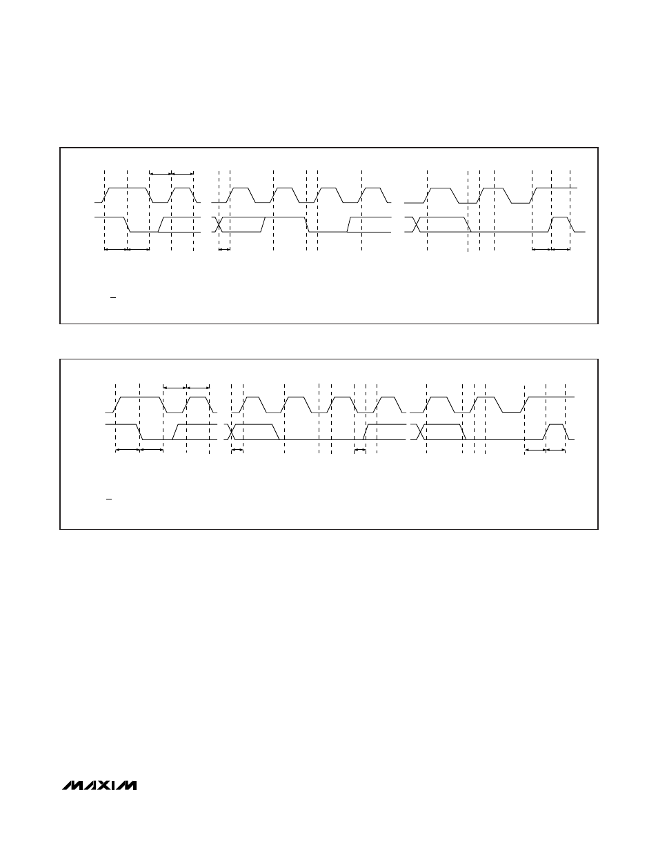
SMBCLK
A = START CONDITION
B = MSB OF ADDRESS CLOCKED INTO SLAVE
C = LSB OF ADDRESS CLOCKED INTO SLAVE
D = R/W BIT CLOCKED INTO SLAVE
A
B
C
D
E
F
G
H
I
J
SMBDATA
t
SU:STA
t
HD:STA
t
LOW
t
HIGH
t
SU:DAT
t
SU:STO
t
BUF
L
M
K
E = SLAVE PULLS SMBDATA LINE LOW
F = ACKNOWLEDGE BIT CLOCKED INTO MASTER
G = MSB OF DATA CLOCKED INTO SLAVE
H = LSB OF DATA CLOCKED INTO SLAVE
I = MASTER PULLS DATA LINE LOW
J = ACKNOWLEDGE CLOCKED INTO SLAVE
K = ACKNOWLEDGE CLOCK PULSE
L = STOP CONDITION
M = NEW START CONDITION
Figure 3. SMBus Write Timing Diagram
SMBCLK
A
B
C
D
E
F
G
H
I
J
K
SMBDATA
t
SU:STA
t
HD:STA
t
LOW
t
HIGH
t
SU:DAT
t
HD:DAT
t
SU:STO
t
BUF
A = START CONDITION
B = MSB OF ADDRESS CLOCKED INTO SLAVE
C = LSB OF ADDRESS CLOCKED INTO SLAVE
D = R/W BIT CLOCKED INTO SLAVE
E = SLAVE PULLS SMBDATA LINE LOW
L
M
F = ACKNOWLEDGE BIT CLOCKED INTO MASTER
G = MSB OF DATA CLOCKED INTO MASTER
H = LSB OF DATA CLOCKED INTO MASTER
I = MASTER PULLS DATA LINE LOW
J = ACKNOWLEDGE CLOCKED INTO SLAVE
K = ACKNOWLEDGE CLOCK PULSE
L = STOP CONDITION
M = NEW START CONDITION
Figure 4. SMBus Read Timing Diagram