Detailed description, Applications information, Pin description – Rainbow Electronics MAX6605 User Manual
Page 4
Detailed Description
The MAX6605 analog output temperature sensor’s out-
put voltage is a linear function of its die temperature.
The slope of the output voltage is 11.9mV/°C, and there
is a 744mV offset at 0°C to allow measurement of nega-
tive temperatures. The MAX6605 has three terminals:
V
CC
, GND, and OUT. The maximum supply current is
10
µA, and the supply voltage range is from +2.4V to
+5.5V for the -40°C to +105°C temperature range and
+2.7V to +5.5V for the -55°C to +125°C temperature
range. The temperature error is <1°C at T
A
= +25°C,
<3.8°C from T
A
= -20°C to +85°C, and <5.8°C from T
A
= -55°C to +125
°C.
Nonlinearity
The benefit of silicon analog temperature sensors over
thermistors is linearity over extended temperatures. The
nonlinearity of the MAX6605 is typically 0.4°C over the
-20°C to +85°C temperature range.
Transfer Function
The temperature-to-voltage transfer function has an
approximately linear positive slope and can be
described by the equation:
V
OUT
= 744mV + (T
✕
11.9mV/
°C)
where T is the MAX6605’s die temperature in
°C.
Therefore:
T (
°C) = (V
OUT
- 744mV) / 11.9mV/
°C
To account for the small amount of curvature in the
transfer function, use the equation below to obtain a
more accurate temperature reading:
V
OUT
= 0.744V + 0.0119V/
°C
✕
T(
°C) +
1.604
✕
10
-6
mV/
°C
2
✕
(T(
°C))
2
Applications Information
Sensing Circuit Board and
Ambient Temperatures
Temperature sensor ICs like the MAX6605 that sense
their own die temperatures must be mounted on, or
close to, the object whose temperature they are intend-
ed to measure. Because there is a good thermal path
between the SC70 package’s metal leads and the IC
die, the MAX6605 can accurately measure the temper-
ature of the circuit board to which it is soldered. If the
sensor is intended to measure the temperature of a heat-
generating component on the circuit board, it should be
mounted as close as possible to that component and
should share supply and ground traces (if they are not
noisy) with that component where possible. This will maxi-
mize the heat transfer from the component to the sensor.
The thermal path between the plastic package and the
die is not as good as the path through the leads, so the
MAX6605, like all temperature sensors in plastic pack-
ages, is less sensitive to the temperature of the surround-
ing air than it is to the temperature of its leads. It can be
successfully used to sense ambient temperature if the cir-
cuit board is designed to track the ambient temperature.
As with any IC, the wiring and circuits must be kept insu-
lated and dry to avoid leakage and corrosion, especially if
the part will be operated at cold temperatures where con-
densation can occur.
The thermal resistance junction to ambient (
θ
JA
) is the
parameter used to calculate the rise of a device junction
temperature (T
J
) due to its power dissipation. For the
MAX6605, use the following equation to calculate the rise
in die temperature:
T
J
= T
A
+
θ
JA
((V
CC
× I
Q
) + (V
CC
- V
OUT
) I
OUT
)
The MAX6605 is a very-low-power temperature sensor
and is intended to drive very light loads. As a result, the
temperature rise due to power dissipation on the die is
insignificant under normal conditions. For example,
assume that the MAX6605 is operating from a +3V sup-
ply at +21.6°C (V
OUT
= 1V) and is driving a 100k
Ω load
(I
OUT
= 10
µA). In the 5-pin SC70 package, the die tem-
perature will increase above the ambient by:
T
J
- T
A
=
θ
JA
((V
CC
× I
Q
) + (V
CC
- V
OUT
) I
OUT
) =
324
°C/W × ((3V × 10µA) + (3V - 1V) × 10µA) = 0.0162°C
Therefore, the error caused by power dissipation will be
negligible.
MAX6605
Low-Power Analog Temperature Sensor
in SC70 Package
4
_______________________________________________________________________________________
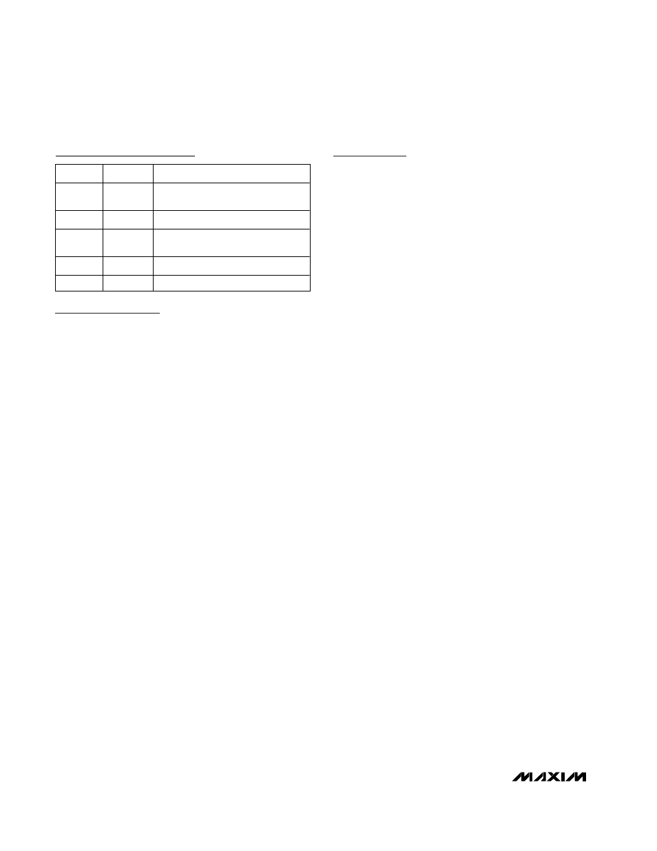
Pin Description
PIN
NAME
FUNCTION
1
V
CC
Supply Input. Decouple with a 0.1µF
capacitor to GND.
2
A
Must be connected to GND.
3
OUT
Temperature Sensor Output,
C
L
≥ 1nF
4
B
Must be connected to V
CC
.
5
GND
Ground