Detailed description, Applications information, Typical operating characteristics (continued) – Rainbow Electronics MAX6673 User Manual
Page 4: Pin description, Pulse-width modulation
Detailed Description
The MAX6672/MAX6673 are low-current (60µA, typ),
local temperature sensors ideal for interfacing with µCs
or µPs. The MAX6672/MAX6673 convert their own tem-
perature into a ratiometric PWM output. The square-
wave output waveform time ratio contains the
temperature information. The output is a square wave
with a nominal frequency of 1.4kHz at +25°C. The tem-
perature is obtained with the following formula:
Temperature (°C) = -200 x (0.85 - t
1
/ t
2
)
3
+ (425 x t
1
/ t
2
) - 273
Where t
1
is a fixed value and t
2
is modulated with the
temperature. Table 1 lists time ratio vs. temperature.
For temperatures greater than +50°C, the temperature
error is primarily first order and the following equation
can be used:
Temperature (°C) = (425 x t
1
/ t
2
) - 273
The MAX6673 has a push-pull output. The rise and fall
times of the MAX6673 output are negligible with
respect to the period; therefore, errors caused by
capacitive loading are minimized.
The output load capacitance should be minimized in
MAX6672 applications because the sourcing current is
set by the pullup resistor. If the output capacitance
becomes too large, unequal rise and fall times distort
the pulse width, thus delivering inaccurate readings.
Applications Information
Pulse-Width Modulation
Interfacing with a µC
The Typical Application Circuit shows the MAX6672/
MAX6673 interfaced with a µC. In this example, the
MAX6672/MAX6673 convert the ambient temperature
to a PWM waveform. The µC reads the temperature by
measuring the t
1
and t
2
periods in software and hard-
ware. The only timing requirements are that the clock
frequency used for timing measurements is stable and
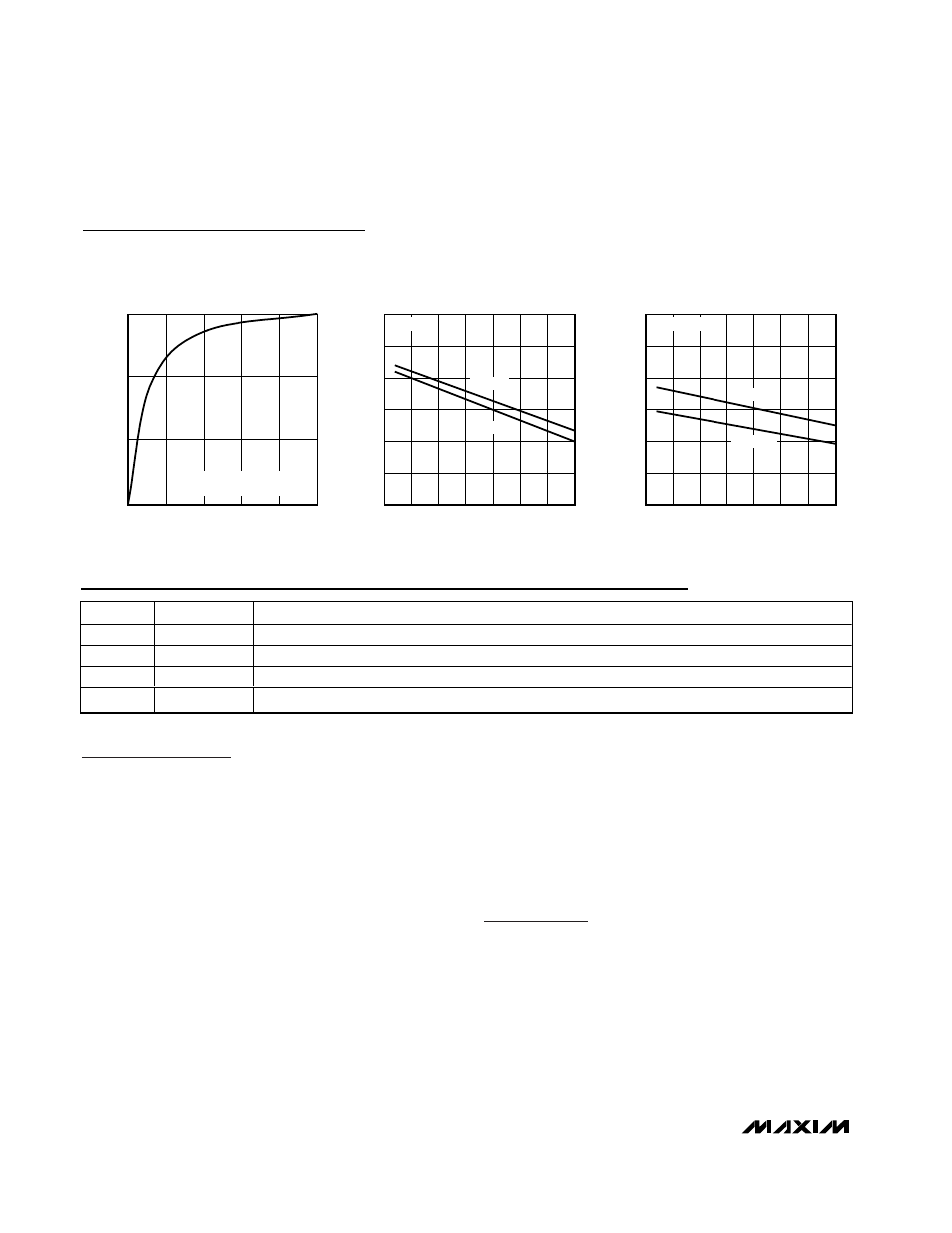
0
8
4
12
16
20
THERMAL RESPONSE
IN STIRRED OIL BATH
MAX6672 toc10
TIME (s)
TEMPERATURE (
°C)
25
50
75
100
TRANSITION FROM +25
°C AIR
TO +100
°C STIRRED OIL BATH
0
10
5
20
15
25
30
-50
0
-25
25
50
75
100
125
OUTPUT SINK CURRENT
vs. TEMPERATURE
MAX6672 toc11
TEMPERATURE (
°C)
SINK CURRENT (mA)
V
OL
= 0.4V
V
CC
= 3.3V
V
CC
= 5V
0
1.0
0.5
2.0
1.5
2.5
3.0
-50
0
-25
25
50
75
100
125
MAX6673 OUTPUT SOURCE CURRENT
vs. TEMPERATURE
MAX6672 toc12
TEMPERATURE (
°C)
SOURCE CURRENT (mA)
V
OH
= V
CC
- 0.5V
V
CC
= 3.3V
V
CC
= 5V
MAX6672/MAX6673
PWM Output Temperature Sensors
in SC70 Packages
4
_______________________________________________________________________________________
Typical Operating Characteristics (continued)
(V
CC
= 3.3V, T
A
= +25°C, unless otherwise noted.)
PIN
NAME
FUNCTION
1
DOUT
Digital Output Pin. PWM output, open-drain output (MAX6672), or push-pull output (MAX6673).
2
N.C.
No Connection. Not internally connected.
3, 4
GND
Pin 3 and Pin 4 must be tied together and connected to ground.
5
V
CC
Positive Supply. Bypass with a 0.1µF capacitor to GND.
Pin Description