Rainbow Electronics ADC0809 User Manual
Page 8
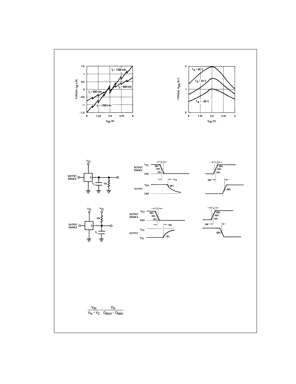
Typical Performance Characteristics
TRI-STATE Test Circuits and Timing Diagrams
Applications Information
OPERATION
1.0 RATIOMETRIC CONVERSION
The ADC0808, ADC0809 is designed as a complete Data
Acquisition System (DAS) for ratiometric conversion sys-
tems. In ratiometric systems, the physical variable being
measured is expressed as a percentage of full-scale which is
not necessarily related to an absolute standard. The voltage
input to the ADC0808 is expressed by the equation
(1)
V
IN
=Input voltage into the ADC0808
V
fs
=Full-scale voltage
V
Z
=Zero voltage
D
X
=Data point being measured
D
MAX
=Maximum data limit
D
MIN
=Minimum data limit
A good example of a ratiometric transducer is a potentiom-
eter used as a position sensor. The position of the wiper is di-
rectly proportional to the output voltage which is a ratio of the
full-scale voltage across it. Since the data is represented as
a proportion of full-scale, reference requirements are greatly
reduced, eliminating a large source of error and cost for
many applications. A major advantage of the ADC0808,
ADC0809 is that the input voltage range is equal to the sup-
ply range so the transducers can be connected directly
across the supply and their outputs connected directly into
the multiplexer inputs, (
Figure 9
).
Ratiometric transducers such as potentiometers, strain
gauges, thermistor bridges, pressure transducers, etc., are
DS005672-16
FIGURE 6. Comparator I
IN
vs V
IN
(V
CC
=V
REF
=5V)
DS005672-17
FIGURE 7. Multiplexer R
ON
vs V
IN
(V
CC
=V
REF
=5V)
t
1H
, t
H1
DS005672-18
t
1H
, C
L
= 10 pF
DS005672-19
t
H1
, C
L
= 50 pF
DS005672-20
t
0H
, t
H0
DS005672-21
t
0H
, C
L
= 10 pF
DS005672-22
t
H0
, C
L
= 50 pF
DS005672-23
FIGURE 8.
www.national.com
8