Applications information – Rainbow Electronics MAX8922L User Manual
Page 9
LDO Output
The LDO is preset to an output voltage of 4.94V and a
100mA current limit (typ). The LDO is powered from IN
and has input overvoltage protection. The LDO is on if a
valid input is present (V
UVLO
< V
IN
< V
OVP
).
Bypass LDO to GND with a 1µF or larger ceramic
capacitor. The LDO can be used to supply low-voltage-
rated USB systems.
Applications Information
Fast-Charge Current Settings
In pulse 1 mode, the maximum charging current is pro-
grammed by an external resistor connected from SETI
to GND (R
SETI
). Calculate R
SETI
as follows:
R
SETI
= 1500V/I
FAST-CHARGE
where I
FAST-CHARGE
is in amperes and R
SETI
is in
ohms. SETI can be used to monitor the fast-charge cur-
rent level in the one-pulse mode (R
SETI
mode). The out-
put current from SETI is 1000µA per ampere of
charging current.
The output voltage at SETI is proportional to the charg-
ing current (I
CHARGE
) when SETI mode is used for the
fast-charge current:
V
SETI
= I
CHARGE
x R
SETI
/1000
The voltage at ISET is nominally 1.5V at the selected
fast-charge current and decreases with charging cur-
rent as the cell becomes fully charged or as the ther-
mal-regulation circuitry activates.
Top-Off Current Settings
The top-off charging current is programmed by an
external resistor connected from MIN to GND (R
MIN
) in
the one-pulse mode (R
SETI
mode). Calculate R
MIN
as
follows:
R
MIN
= 150V/I
MIN
where I
MIN
is in amperes and R
MIN
is in ohms.
Capacitor Selection
Connect a 2.2µF ceramic capacitor from BAT to GND
for proper stability. Connect a 1µF ceramic capacitor
from IN to GND. Use a larger input bypass capacitor for
high charging currents to reduce supply noise. All
capacitors should be X5R dielectric or better. Be aware
that some capacitors have large-voltage coefficients,
and should be avoided.
MAX8922L
30V Li+ Linear Battery Charger
with GSM Test Mode in 3mm x 2mm TDFN
_______________________________________________________________________________________
9
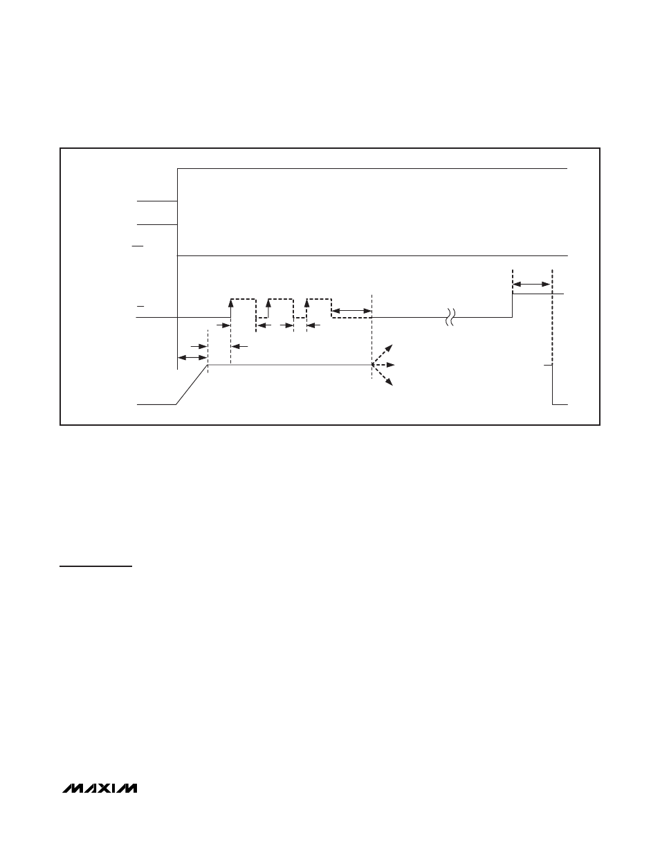
DC
EN
t
SOFTSTART
I
FAST
1
2
3
400mA SETTING (DEFAULT)
SETI MODE (1 PULSE + > 4ms LOW)
OFF
POK
HIGH IMPEDANCE
PULL LOW
> 4ms
NO TIME LIMIT
90mA MODE (2 PULSES + > 4ms LOW)
GSM TEST MODE
(3 PULSES + > 4ms LOW)
> 4ms
t
HIGH
t
LOW
Figure 3. Charge-Current Programming