Figure 3 – Banks Power Ford Motorhomes: (Gas ’93 - 97 7.5L Class-C) PowerPack system (Class-C) For Use w_ 460 EFI Engine User Manual
Page 7
NOT kink or deform the tubes.
9.
unbolt and remove exhaust manifolds from
engine, loosen any brackets attached to
exhaust manifold bolts as required (other side of
brackets may be left attached to engine during
manifold removal). remove sparkplug wire heat
shields, if equipped. discard heat shields as they
will not be reused.
10.
inspect the exhaust manifold flange
surfaces on the cylinder heads. remove
any foreign material from these surfaces that
might prevent proper manifold sealing. if cylinder
heads have been heavily eroded from leaking
factory manifolds, exhaust manifold gaskets will
be required, or the heads must be removed and
the exhaust flange area surfaced as necessary.
otherwise, no gaskets are used between the
banks torquetube manifolds and cylinder head,
as the torquetubes have machined flanges like
the original factory iron manifolds.
11.
install right-hand banks torquetube
exhaust manifold from under the vehicle.
see caution note on jacking and raising vehicle in
general installation practices section. install all
bolts finger-tight, then tighten bolts from the
center out. use a dab of anti-seize lubricant
(provided) on the bolt threads where they enter
the head. see Figure 1 for bolt locations.
reconnect air injection tube (if used) to two-bolt
flange at rear of exhaust manifold head flange.
(only manifolds for air injected engines will have
this flange.)
use new gasket, provided, two
1
⁄
4
-28 x
3
⁄
4
hex bolts,
and four
1
⁄
4
” circle-lock washers. washers are
used in pairs on each bolt, the ramps on the
surface of each washer must face each other
when installed on bolt. see Figure 1 for proper
washer installation.
12.
install left-hand banks torquetube exhaust
manifold from under the vehicle. use two
bolts to temporarily hang and position the
manifold on the cylinder head. thread egr tube
and air injection tube (if equipped) in fittings on
banks exhaust manifold. note: early-model air
injection systems require an adapter nipple
(supplied) for hook-up see Figure 2.
because of the tight confines, we suggest that
the egr tube (if equipped) be tightened into the
manifold with the manifold loosely attached to
the head (this allows for some additional freedom
of movement). in some cases, the egr and air
injection tubes may have to be tightened with the
manifold completely separated from the head,
then bolted to the head when wrenching the
tubes is completed. air injection tube may be
loosened from its upper support bracket to aid in
alignment during installation. a dab of anti-seize
on the tube threads will aid in assembly.
once this procedure is complete, install remaining
manifold bolts finger tight, with anti-seize applied.
see Figure 2 for bolt location. bolt dipstick tab to
spacer on manifold bolt as indicated in Figure 2.
13.
reinstall sparkplugs and sparkplug wires.
do not reinstall factory spark plug heat
shields. they are unnecessary with the torque
tubes, and may cause poor engine performance
due to arcing.
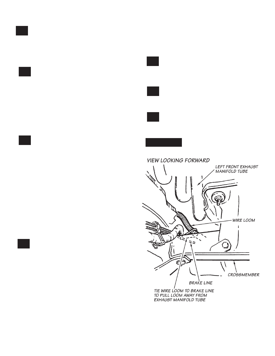
14.
use a plastic cable tie, provided, to pull
wire loom away from left front manifold
tube as shown in Figure 3 by tying wire loom to
brake line.
15.
install new y-pipe between torquetube
manifold outlets and catalytic converter.
figure 3
7
96360 v.4.0
7