Figure 8 figure 7 – Banks Power GM Motorhomes: (Gas ’01 - 10 8.1L Workhorse) PowerPack & Stinger systems '01-04 Class-A MH, P-series User Manual
Page 8
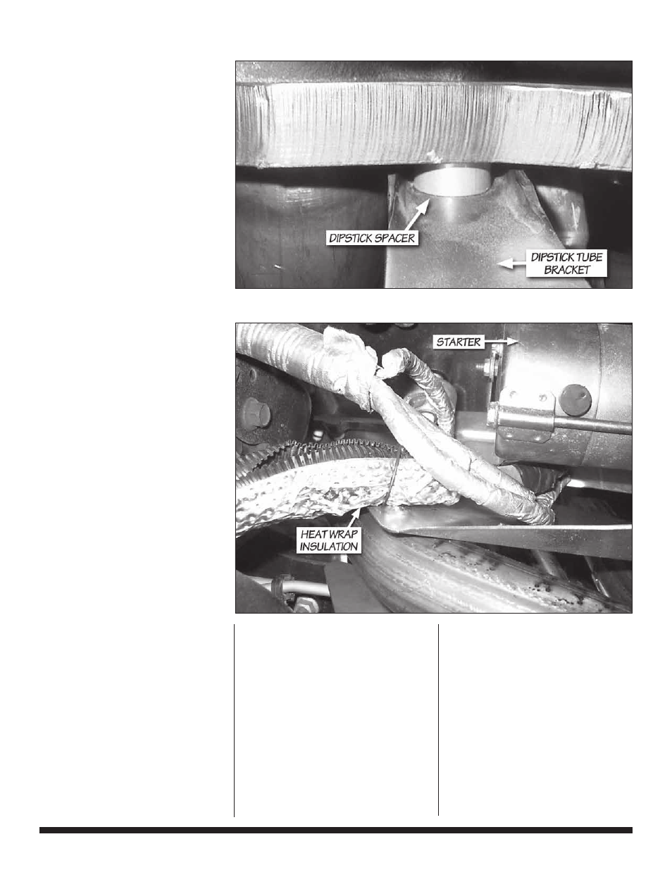
17.
Reinstall the dipstick
tube and o-ring. Using
the single 8 mm x 30 mm
manifold bolt and spacer
provided, attach the bracket
to the flange as shown in
Figure
7
. Torque the 8 mm
x 30 mm bolt to 26 ft-lbs.
Re-secure the bracket to the
alternator support using the
bolt previously removed.
Re-install the spark plugs
and spark plug wires in their
original locations.
18.
If applicable, bolt the
EGR tube to the TorqueTube
manifold using the supplied:
(1) EGR gasket
(2)
5
⁄
16
-18 x 1.0” bolts
(2)
5
⁄
16
-18 crimplock nuts
(4)
5
⁄
16
washers
It may be necessary to rotate
the flange on the EGR tube to
align with the flange on the
TorqueTube manifold. Torque
the EGR hardware to 25 ft-lbs.
19.
Attach the supplied
heat wrap insulation to the
starter cable extension, if
installed, using the steel wire
ties provided. Relocate and
insulate wires to shield the
cable from the heat source
(see Figure
8
).
20.
Place a conical seal
in the flare on the right
side headpipe. Attach the
headpipe and conical seal
to the right-side TorqueTube
manifold using
(2)
3
⁄
8
-16 x 1
3
⁄
4
” bolts
(2)
3
⁄
8
SAE washers
Tighten the bolts just enough
to hold the headpipe in place.
21.
Insert the balance tube
onto the installed right side
headpipe. Slide (2) 2
1
⁄
4
”
clamps over the balance tube.
Place a conical seal in the
flare on the left side headpipe.
Attach the headpipe to the
left-side TorqueTube manifold
and balance tube. Insert
the end of the balance tube
into the headpipe. Loosely
assemble the left headpipe to
the TorqueTube using:
(2)
3
⁄
8
-16 x 1
3
⁄
4
-inch bolts
(2)
3
⁄
8
SAE washers
Using th e supplied zip ties,
secure any wire harnesses
away from the
H-pipe (see Figure
9
).
Figure 8
Figure 7
8 |
9 6 4 3 2 v . 5 . 0