Velleman DVM13MFC2 User Manual
Page 5
DVM13MFC2
VELLEMAN
- 5 -
a.
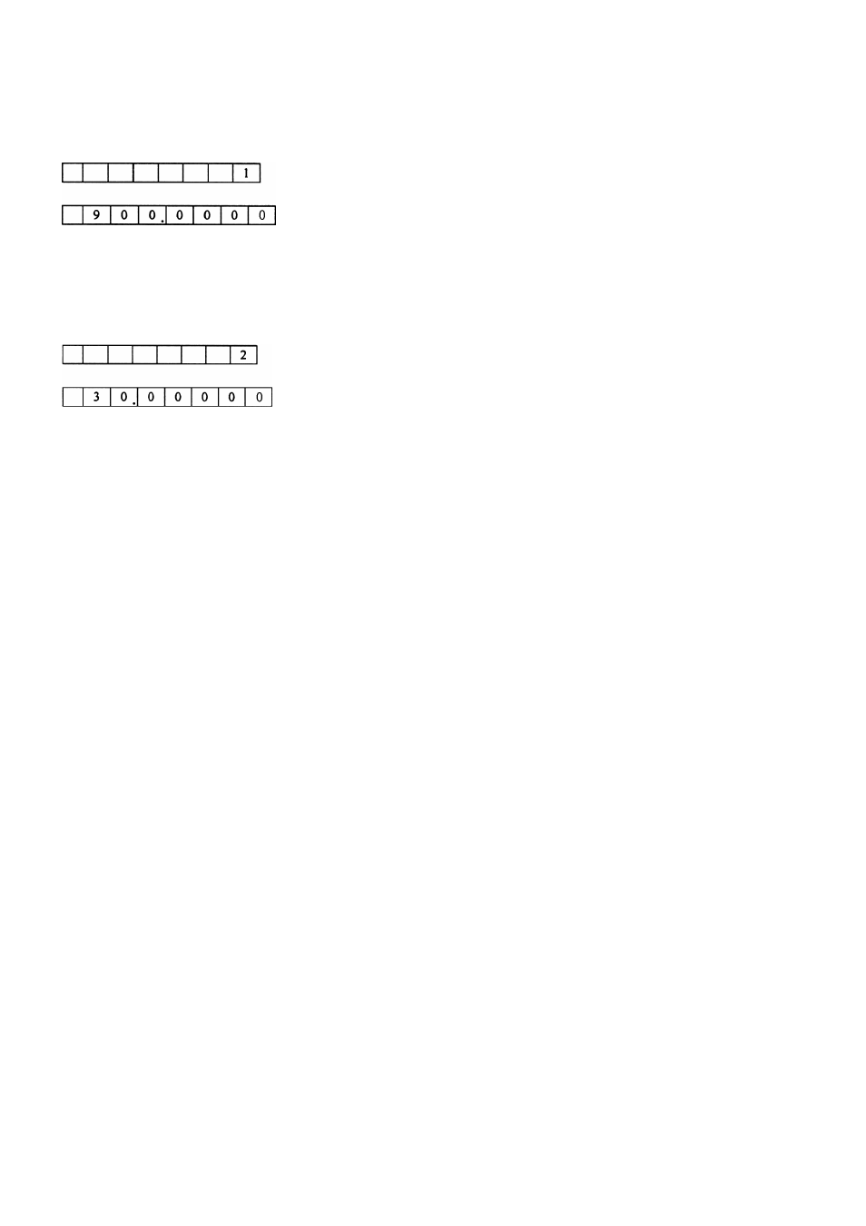
Example 1: Measuring an analogue handset
Connect the test cable with the input from channel B and set the FUNCTION key to the 1-step position. Select the
gate time (adjust manually from 100 msec to 10 sec). The LED display will read:
b.
Example 2: Measuring a 30Mhz intercom emission frequency
Set the FUNCTION to the 2-step position and select the gate time (adjust manually from 100 msec to 10 sec). The
LED display will read:
c.
Example 3: Measuring a self-oscillating frequency (e.g. from a telephone, intercom etc.)
Set the FUNCTION key to the 2-step position. Connect one end of a cable with 5pF capacitance to the red clamp;
use the other end to measure the frequency by touching the contact point.
6. Warnings
•
When measuring a high-voltage or strong RF signal, make sure that the cables are in series and have a large
capacitance to avoid damage.
•
Press the RESET button once to reset the device or turn off the device in case the device is not working
appropriately.
•
When there is no input signal, the display may not necessarily read “0”. This is absolutely normal and does not
affect the measurements or the accuracy.
•
Do not expose the device to extreme temperatures, humidity, dirt, dust etc. Do not open the device to avoid lethal
electroshocks.
•
A strong interference will reduce the sensitivity when measuring.
7. Technical Specifications
Channel A (0.01Hz ~ 50MHz)
Frequency Range
DC couple 0.01Hz to 100Hz
AC couple 100Hz to 50MHz
Sensitivity
AC: 100Hz ~ 50MHz < 80m Vrms
DC: 0.01Hz ~ 1Hz ≤ 500m Vp-p
1Hz ~ 100Hz ≤ 80m Vrms
Impedance
1 Mohms
Attenuator
X1, X20
Max. Safety Voltage
30V (DC/AC peak)
Channel B (50MHz ~ 2.4GHz)
Frequency Range
from 50MHz to 2.4GHz
Sensitivity
50MHz ~ 1.2GHz ≤ 50m Vrms
1.2GHz ~ 2.4GHz > 80m Vrms
Coupling
AC only
Impedance
50 ohms
Max. Safety Voltage
3V
1-step
900MHz
2-step
30MHz