Velleman DVM52IT User Manual
Page 3
DVM52IT
VELLEMAN
3
5.1 General Specifications
Max. voltage between terminals and earth
1000V dc or ac
Measuring Method
Dual-slope integration A/D converter
Sampling Time
±0.4sec.
LCD Height
22mm
Max. Display
1999 points (3 ½ digits)
Polarity Indication
‘-‘ indicates negative polarity
Overrange Indication
‘1’ or ‘-1’ is displayed
Displayed Measuring Unit
Unit of electrical capacity
Power Supply
6 AA-batteries of 1.5V (alkaline batteries are recommended)
Power Consumption
±5mA (100Vdc, 750Vac, 200
Ω
, )
±30mA (200M
Ω
, 250V)
±50mA (200M
Ω
/500V)
±100mA (2000M
Ω
/1000V)
Battery-Low Indication
“
”-symbol is displayed
Operating Temperature
0 to 40°C (32 to 104°F)
Operating Humidity
< 85%RH
Storage Temperature
-10 to +50°C (10 to 122°F)
Dimensions
192 x 122 x 55mm
Weight
± 545g (with batteries)
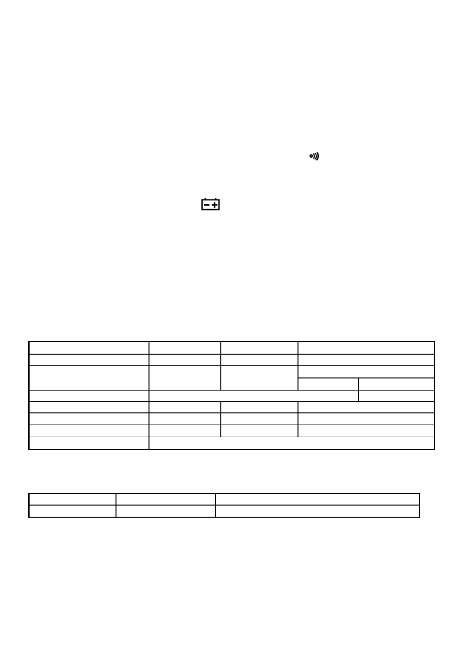
5.2 Electrical Specifications
5.2.1. Insulation Resistance
Range
200M
Ω
Ω
Ω
Ω
/ 250V
200M
Ω
Ω
Ω
Ω
/ 500V
2000M
Ω
Ω
Ω
Ω
/ 1000V
Test Voltage
250Vdc ± 10%
500Vdc ± 10%
1000Vdc ± 10%
0 ~2000M
Ω
Measuring Ranges
0 ~200M
Ω
0 ~200M
Ω
0 ~1000M
Ω
1000 ~2000M
Ω
Accuracy
± 3% rdg ± 5 digits
± 5% rdg ± 5 digits
Output Voltage on Open Circuit
250V ± 10%
500V ± 10%
1000V ± 10%
Min. Output Voltage
225V at 0.25M
Ω
450V at 0.5M
Ω
900V at 1M
Ω
Test Current (approx.)
1mA at 0.25M
Ω
1mA at 0.5M
Ω
1mA at 1M
Ω
Output Short-Circuit Current
≤
2.5mA
5.2.2. AC Voltage
Range
Resolution
Accuracy
700V
1V
±1.2% of rdg + 5 digits
Input Impedance
10M
Ω
Max. Input Voltage
700V rms AC or 1000V DC
Frequency Range
40 to 400Hz
Response
average, calibrated in rms of a sine wave