Velleman VDP1401RGLD5 User Manual
Page 5
10.01.20
res
•
For
the
•
Adj
•
Ma
b) DMX-
•
Wh
and
VD
scr
•
A D
or
dig
res
in t
c) gener
•
Ma
coo
•
Hav
•
Co
•
The
7. Op
Refer to t
•
Make
laser
•
To tu
turns
•
The l
Sound c
•
Set
•
Set
DMX con
•
All
sig
the
ind
•
Wh
par
sim
num
•
In
1 (
•
Use
•
Ref
Ch
011
sult in serious in
r truss-mountin
e (folded) brack
just the desired
ke sure there is
-512 connectio
hen applicable, c
d the other side
DP1401RGLD5’
reened cable wit
DMX terminator
is in an electrica
gital control sign
sistor between p
the chain.
ral
ke sure there is
oling.
ve a qualified e
nnect the devic
e installation ha
eration
the illustrations
e sure the laser
r projector. Inse
urn on the laser
s on.
aser can operat
ontrolled mod
t all DIP switche
t the microphon
ntrolled mode
DMX-controlled
nals. This digita
e DMX controller
dividual address
hen all devices h
rticular channel
multaneously. If
mber. Changing
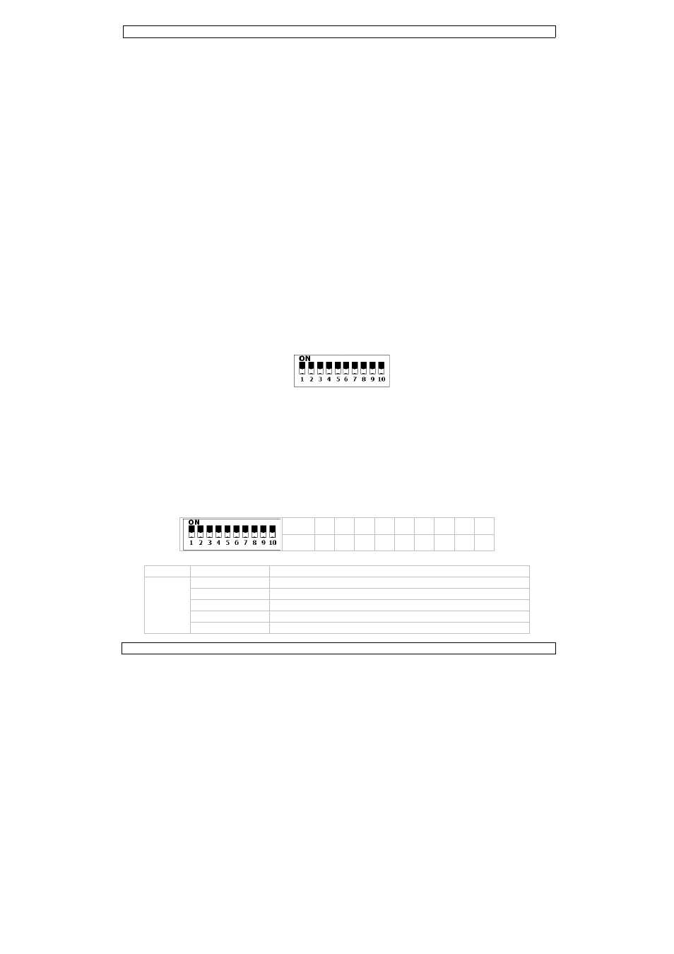
case of the 5-ch
CH1~5), the se
e the DIP switch
fer to the table
hannel DMX-5
CH1
0
51
102
153
204
njuries.
g, use an appro
et.
d inclination ang
s no flammable
on
connect an XLR
e to the male 3-
’s can be linked
th XLR input an
is recommende
ally noisy enviro
nal by electrical
pins 2 and 3, wh
s no flammable
lectrician carry
e to the mains w
as to be approve
s on page 2 of th
projector is tur
ert the other end
projector, use t
te in two modes
de
es [4] to the OF
ne [2] sensitivit
d devices need a
al start address
r. The same sta
can be set for
have the same a
. In other words
you set individ
g the settings of
hannel VDP140
econd unit to 6 (
hes [4] to set t
below for an ov
512 value
~ 50
So
~ 101
Aut
2 ~ 152
Se
3 ~203
Co
4 ~ 255
No
VDP1401
5
opriate clamp (n
gle via the moun
material within
cable to the fem
pin XLR input o
through serial
d output connec
ed for installatio
onment (e.g. di
noise. The DMX
hich is then plug
material within
out the electric
with the power
ed by an expert
his manual.
ned off. Insert t
d of the power c
the on/off switc
s: sound contr
FF position to en
ty with the sens
a digital start ad
is the channel n
arting address ca
every device.
address, all the
s: changing the
ual addresses, e
f one channel w
01RGLD5, you
(1 + 5) (CH6~1
he appropriate
switch 1
2
value 1
2
verview of the c
und active
to
lect pattern mo
ntrol mode
output
RGLD5
not incl.) and fit
nting bracket an
a 50cm radius
male 3-pin XLR
f the VDP1401
linking. The link
ctors.
ons where the D
scos). The term
X terminator is s
gged into the XL
a 50cm radius
al connection.
plug. Don’t con
t before the dev
the power plug
cable into the m
ch [7] and turn
rolled or DMX c
nable sound con
sitivity knob [3]
ddress so that t
number from w
an be used for a
units will “listen
settings of one
each device will
will only affect th
will have to set
10), the third to
DMX address.
2 3 4 5
2 4 8 1
ontrol signals p
Control Pr
de
an M10 bolt th
nd tighten the b
of the device.
output of a con
1RGLD5. Multip
king cable shou
DMX cable has to
minator prevents
simply an XLR p
LR output socke
of the device an
nect it to a dim
vice is taken into
into the power
mains.
the safety key.
controlled mod
ntrolled mode.
].
he correct devic
hich the device
a whole group o
n” to the contro
e channel will af
“listen” to a se
he device in que
the start addre
11 (6 + 5) (CH
5 6 7 8
6 32 64 12
er channel.
rograms
©Vellem
rough the centr
racket screws.
ntroller (not incl
le
ld be a dual cor
o run a long dis
s corruption of t
plug with a 120Ω
et of the last dev
nd there is suffi
ming pack.
o service.
input [8] of the
The power LED
de.
ce responds to t
starts to “listen
of devices or an
ol signal on one
ffect all devices
eparate channel
estion.
ess of the first u
H11~15), and so
8 9
28 256
man nv
re of
.)
re,
tance
the
Ω
vice
cient
e
D [1]
the
n” to
unit to
o on.