Velleman VTLAN6 User Manual
Page 5
VTLAN6
V. 01 – 07/10/2013
5
©Velleman nv
1. Set the on/off switch [2] in the ON position. The indicator [1]
blinks.
To execute the test at a slower pace, set the on/off switch in the
S (‘slow’) position. The indicator blinks slower.
2. Insert one end of the cable under test into the socket in the
master: [3] for RJ45, [4] for RJ11/RJ12.
3. Insert the other end of the cable into the socket in the remote
[7] for RJ45, [8] for RJ11/RJ12.
The cable test lights on the master [5] and on the remote [6]
light up in sequence.
4. After testing, remove the cable from master and remote and set
the on/off switch in the OFF position.
5.2
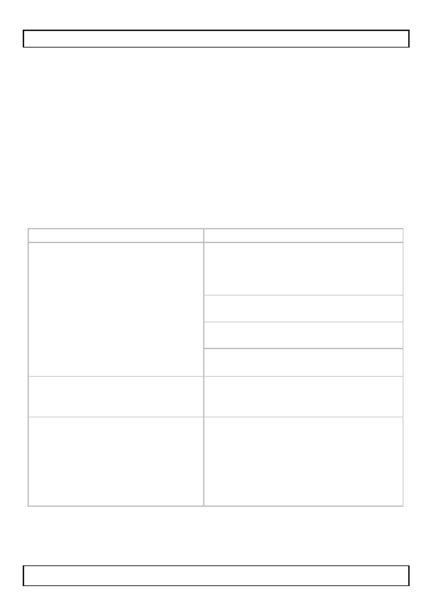
Test results: exam ples
Description
Sequence
Good connection: all indicators
light up in sequence.
Note: Indicator G lights up
only for cables with a ground
(GND).
master:
1 2 3 4 5 6 7 8 G
(8P8C)
remote:
1 2 3 4 5 6 7 8 G
(8P8C)
master:
1 2 3 4 5 6 (6P6C)
remote:
1 2 3 4 5 6 (6P6C)
master:
1 2 3 4 (6P4C)
remote:
1 2 3 4 (6P4C)
master:
1 2 (6P2C)
remote:
1 2 (6P2C)
Open circuit: wire 2 is broken,
indicator 2 does not light up on
master and remote.
master:
1
2
3 4 5 6 7 8
remote:
1
2
3 4 5 6 7 8
Open circuits: wires 2 and 5
are broken, indicators 2 and 5
do not light up on master and
remote.
Note: If less than two wires in
the cable are connected, none
of the indicators lights up.
master:
1
2
3 4
5
6 7 8
remote:
1
2
3 4
5
6 7 8