Specification, Installation, Approvals to order specify – VEGA TP32 Series User Manual
Page 2
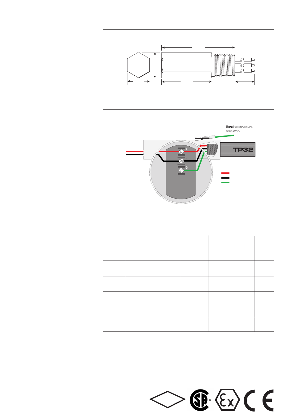
+ve
-ve
Earth
Specification
All figures typical at 25°C (77°F) unless otherwise stated
Maximum surge current
10kA peak (8/20µs waveform)
Leakage current
Line-line:
< 1µA at working voltage
Line-earth:
< 1µA at 120V common-mode
Working voltage
±32V dc maximum
±120V peak (or DC) maximum common-mode
Maximum continuous operating voltage
35V
Limiting voltage
Line-line with 250mm cable:
< 49V (10A, 10/1000µs pulse)
Line-earth with 75mm cable:
<635V (3kA, 8/20µs waveform)
<635V (6kV, 1.2/50µs waveform)
Line resistance
No resistance introduced into the loop
Capacitance
Line-line:
< 50pF
Line-earth:
< 100pF
Attenuation
7·8KHz–7.5MHz monotonic & better than –1dB
typical bandwidth, 150MHz on 100Ω system
Ambient temperature limits
T6
–40°F to +140°F (–40°C to +60°C)
T5
–40°F to +185°F (–40°C to +85°C)
Humidity
5% to 95% RH (non-condensing)
Electrical connections
3 flying leads: line 1 & line 2 plus
non-polarised earth
Wire size:
32 / 0.2 (1.0mm
2
, 18 AWG)
Lead length:
250mm minimum supplied
≤ 75mm recommended
Casing
ANSI 316 stainless steel hexagonal barstock,
male thread
Threads
TP32-N
1
/
2
” NPT
TP32-I
20mm ISO (M20 x 1.5)
TP32-G
G
1
/
2
” (BSP
1
/
2
inch)
Weight
175g (6.18oz)
Dimensions
See figure 1
ATEX compliance
See Approvals table for details
EMC compliance
BS EN 61643-1
Electrical Safety
EEx ia IIC T6, Ceq=0, Leq=0; the unit can be
connected without further certification into any
intrinsically safe loop with open circuit voltage
<60V and input power <1.2W.
EEx d IIC T6; the unit is apparatus-approved to
explosionproof (flameproof) standards, and can
be fitted into a similarly approved housing.
Installation
The TP32 is designed for mounting directly into an
unused conduit entry on a fieldbus transmitter
housing (see figure 2). Generally, two such entries are
provided, one of which is used for the bus wiring. On
the unused entry, the blanking plug or other closure
device is removed and an appropriately threaded
TP32 screwed into its place. The transmitter
specification should provide information indicating the
required thread type. TP32 units can be installed
using thread adaptors (such as a tee piece) if
necessary, including certified adaptors in hazardous
area applications. For applications where two conduit
entries are not provided or where both are used for
electrical connections, TP32 units can be housed in
conventional conduit hub or junction boxes, provided
access to the loop terminals is possible.
904-023 0
1
75mm
(2.95")
27mm
(1.07")
55mm
(2.17")
Lead length
250mm (9.85")
minimum supplied
23mm
(0.91")
Dimensions across flats 23mm (0.91")
Figure 1 Dimensions
Figure 2 Connection detail for a typical transmitter
Approvals
To order specify -
TP32-N
1
/
2
” NPT thread
TP32-N-NDI
1
/
2
” NPT thread, with EEx ia, EEx d, FM and CSA approval
TP32-I
20mm ISO thread
TP32-I-NDI
20mm ISO thread, with EEx ia, EEx d, FM and CSA approval
TP32-G
G
1
/
2
” (BSP
1
/
2
inch)
TP32-G-NDI
G
1
/
2
” (BSP
1
/
2
inch), with EEx ia, EExd, FM and CSA approval
Note: In accordance with our policy of continuous improvement, we reserve the right to change the product’s specification without notice.
Telematic and Atlantic Scientific surge protection devices
are designed and manufactured by MTL Surge Technologies.
MTL Surge Technologies
Power Court, Luton, Bedfordshire, England LU1 3JJ
Tel: +44 (0)1582 723633 Fax: +44 (0)1582 422283
E-mail: [email protected] WWW: www.mtlsurge.com
A member of the MTL Instruments Group plc
Country
Standard
Certificate/File Approved
for
Product
(Authority)
No.
UK (BASEEFA)
EN 50014:1997 + Amendments 1 & 2
BAS00ATEX1258X
EEx ia IIC T6 (T
amb
= -40 to 60°C)
TP32-N-NDI
EN 50020:1994, EN 50284:1999
EEx ia IIC T5 (T
amb
= -40 to 85°C)
TP32-I-NDI
TP32-G-NDI
UK (BASEEFA)
EN 50014:1997 + Amendments 1 & 2
BAS00ATEX2146X
EEx d IIC T6 (T
amb
= -40 to 60°C)
TP32-N-NDI
EN 50018:2000
EEx d IIC T5 (T
amb
= -40 to 85°C)
TP32-I-NDI
TP32-G-NDI
Atex Directive
To be confirmed
TML02ATEX0032X
Ex n II T6 (-40°C amb <+60°C) TP32-N 94/9/EC Eex n II T5 (-40°C amb <+85°C) TP32-I TP32-G USA (FM) Class Nos. 3600 (1998), 3610 (1999), 311208 Intrinsically Safe: TP32-N-NDI 3611 (1999), 3615 (1989), 3810 incl. I, II, III/1/A-G, I/0/IIC TP32-I-NDI Supp 1 (1995-07 (1989-03), Explosionproof: I/1/A-D TP32-G-NDI ANSI/NEMA 250 (1999), Non incendive: I/2/A-D, I/2/IIC ISA0S12.0.01 (1998) Dust ignition proof: II,III/1/EFG Canada (CSA) C22.2 No. 30 152423 Class I, Grp A-D TP32-N-NDI C22.2 No. 1010 (LR 36637) Class II, Grp E-G TP32-I-NDI F M APPROVED
Special protection: II/2/FG
TP32-G-NDI