VEGA KFD0-SCS-Ex1.55 User Manual
Kfd0-scs-ex1.55 smart repeaters, Composition
1
122
60
9_
EN
G.xm
l
2
003
-03-
2
5
Subject to reasonable modifications due to technical advances.
Copyright Pepperl+Fuchs, Printed in Germany
Pepperl+Fuchs Group • Tel.: Germany +49 621 776-0 • USA +1 330 4253555 • Singapore +65 67799091 • Internet http://www.pepperl-fuchs.com
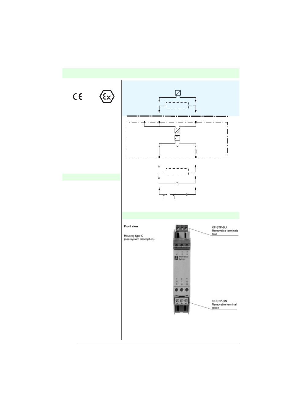
KFD0-SCS-Ex1.55
SMART repeaters
Field circuit EEx ib IIC
Transmitter
Positioner
I/P converter
Current source
4 mA ... 20 mA
or
Voltage supply
Saf
e area
Hazar
dous area
Measuring resistors
Supply circuit
SMART
communicator
SMART
communicator
2-
U/I
1+
2-
2-
3-
2-
1+
2-
1+
8-
8-
9+
9+
8-
9+
8-
9+
50 mA
33 V
I
?
Composition
Transmission range 4 mA ... 20 mA
• 1-channel
• Field circuit EEx ib IIC
• Loop powered
• Lead monitoring
• Conductive for HART communication
(galvanically isolated)
• Universal application for transmitters,
position controllers and I/P
converters
• Only 5 V voltage drop
• Test sockets for HART
• EMC acc. to NAMUR NE 21
The universal module
KFD0-SCS-Ex1.55 does not require
auxiliary power for the isolation of
4 mA ... 20 mA current loops. It is
therefore, low in cost and has a
noticeably low power loss as compared
to active isolator modules. The module
isolates 4 mA ... 20 mA signals from
transmitters and positioners and is
therefore, bidirectionally HART
compatible. The HART transmitters and
HART positioners may thus, be
configured in the safe area as well as
the hazardous area. The low 5 V
voltage drop also allows for transmitter-
applications with unstable power
sources in the range of
20 V DC ... 30 V DC.
In addition, the voltage drop across the
resistance (load) of the active
measurement input must be considered
when calculating the field voltage
(terminals 1+ and 2-).
Lead breakage monitoring is possible
by means of the reaction of the field
current signal to the safe area, which
means the control system must monitor
whether the 4 mA ... 20 mA range was
exceeded or fallen short of.
The module may also be used for
controlling Ex-i valves, light signals, etc.
based on the internal voltage limits
(safe area). Terminals 8- and 9+ in this
case are driven with a 24 V binary
signal.
Function