4 proof test – VEGA VEGASWING 66 - Relay With SIL qualification User Manual
Page 23
23
6 Setup
VEGASWING 66 • - Relay
44950-EN-130805
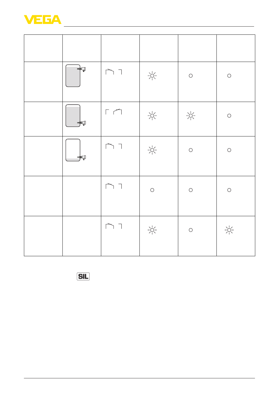
Level
Switching sta-
tus
Signal lamp -
green
Voltage supply
Signal lamp -
yellow
Switching sta-
tus
Signal lamp
- red
Fault message
Mode max.
Overflow pro-
tection
5
3
4
(8)
(6) (7)
Relay deener-
gized
Mode min.
Dry run protec-
tion
5
3
4
(8)
(6) (7)
Relay energized
Mode min.
Dry run protec-
tion
5
3
4
(8)
(6) (7)
Relay deener-
gized
Failure of the
supply voltage
(max./min. mode)
any
5
3
4
(8)
(6) (7)
Relay deener-
gized
Fault
any
5
3
4
(8)
(6) (7)
Relay deener-
gized
6.4 Proof test
To find out possible undetected, dangerous failures, a proof test must
be carried out in adequate time intervals to check the safety function.
It is the user's responsibility to choose the type of testing.
You will find further instructions in the Safety Manual.
The following options are available for carrying out the proof test:
1. Short interruption of the supply line to the sensor
Average coverage (detected errors)
2. Dismounting of the sensor and immersion in the original medium
High coverage (detected errors)
3. Filling of the vessel up to the switching point
High coverage (detected errors)