4 mounting, 1 mounting steps – VEGA Supplementary electronics For 4 … 20 mA_HART and power pack User Manual
Page 7
7
4 Mounting
Supplementary electronics • For 4 … 20 mA/HART and power pack
41033-EN-140108
4 Mounting
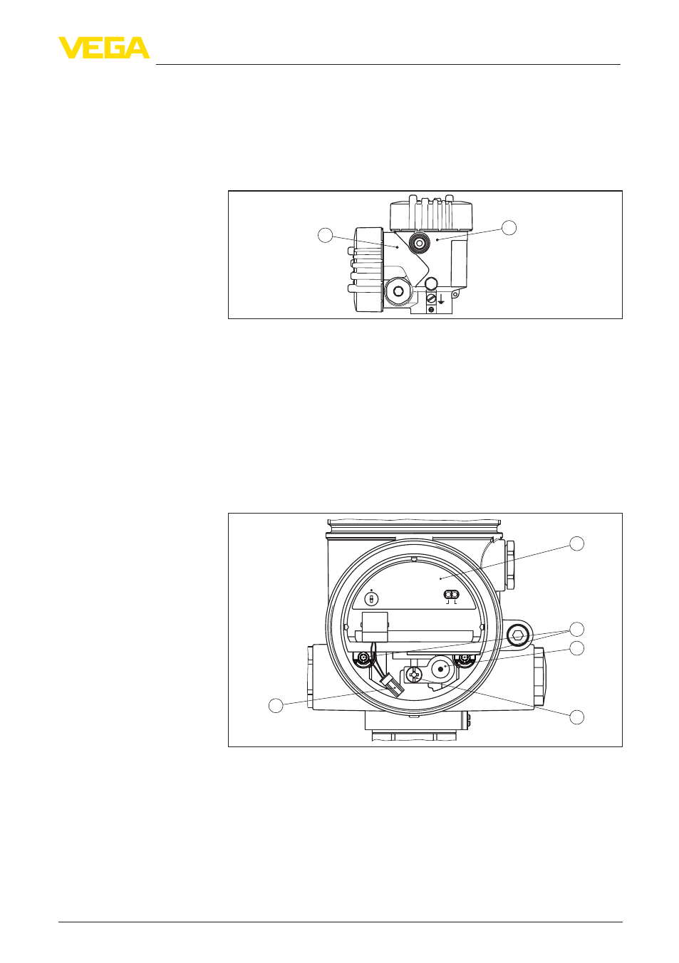
4.1 Mounting steps
The supplementary electronics is mounted in the power supply com-
partment. The following illustration shows the position of the power
supply compartment in the double chamber housing.
2
1
Fig. 1: Position of the power supply and electronics compartment
1 Power supply compartment (accumulator insert)
2 Electronics compartment
Proceed as follows:
1. Unscrew housing cover of the power supply compartment
2. Loosen plug connector to the charging socket
3. Loosen fixing screw of the charging socket and remove charging
socket
4. Loosen the two holding screws of the accumulator insert with a
screwdriver (Torx size T 10 or slot size 4)
0
5
1
6
2
7
3
8
4
9
modes
4 ON/OFF
3 ON/OFF 1h
1,2 OFF
Charge
Accu
5..9 auto cycle
1
2
+
( )
(-)
1
2
3
5
4
Fig. 2: Power supply compartment with accumulator insert
1 Accumulator insert
2 Holding screws
3 Charging socket
4 Fixing screw charging socket
5 Connection cable with plug connector to the charging socket
5. Pull out the previous accumulator socket with the dismounting
tool
6. Insert the new accumulator insert carefully.
Mounting steps