5 connect the sensor to the external housing, 1 preparing the connection, 2 connection procedure – VEGA VEGABAR series 80 External housing User Manual
Page 10
10
5 Connect the sensor to the external housing
External housing • For pressure transmitter VEGABAR series 80
45081-EN-131119
5 Connect the sensor to the external
housing
5.1 Preparing the connection
Follow the instructions in the operating instructions manual of the
sensor.
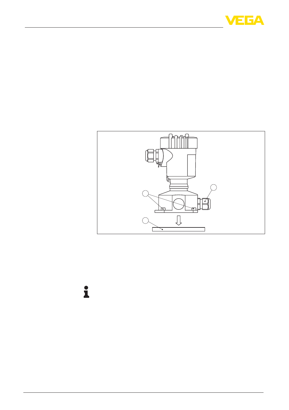
5.2 Connection procedure
Proceed as follows to connect the external housing:
1. Loosen the four screws on the base with a hexagon key or fork
wrench
2. Remove the mounting plate from the base
3
2
1
Fig. 6: Removing the mounting plate on the base
1 Screws
2 Wall mounting plate
3 Cable gland
3. Loop the connection cable through the cable entry on the housing
base
1)
Tip:
With plastic housing, the cable gland can be mounted in three posi-
tions each displaced by 90°. Simply exchange the cable gland against
the blind plug in the fitting threaded hole.
4. Connect the wire ends as described in chapter "Connection plan".
Take note of the numbering.
5. Connect the screen to the internal ground terminal, connect the
outer ground terminal to potential equalisation
1)
The connection cable comes pre-assembled. If necessary, shorten it to the
requested length, cut the breather capillaries clean. Remove approx. 5 cm of
the cable mantle, strip approx. 1 cm insulation from the ends of the individual
wires. After shortening the cable, fasten the type plate with support back on
the cable.