6 setup, 1 general information, 2 adjustment elements – VEGA VEGACAP 67 - two-wire User Manual
Page 20
20
6 Setup
VEGACAP 67 • - two-wire
31317-EN-130916
6 Setup
6.1 General information
The figures in brackets refer to the following illustrations.
On the electronics module you will find the following display and
adjustment elements:
•
DIL switch for measuring range selection
•
Control lamp
Note:
As a rule, always set the mode with the mode switch of the signal
conditioning instrument before starting setup VEGACAP 67. The
switching output will change if you set the mode switch afterwards.
This could possibly trigger other connected instruments or devices.
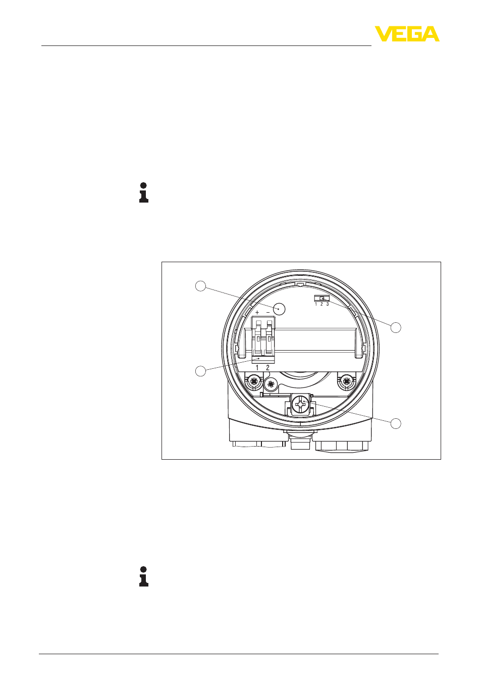
6.2 Adjustment elements
4
1
2
3
Fig. 14: Electronics module - Two-wire output
1 DIL switch for measuring range selection (with compensation button)
2 Ground terminal
3 Connection terminals
4 Control lamp
A failure can be displayed with closed housing (only plastic housing),
see operating instructions manual of the "Signal conditioning instru-
ment".
Note:
Screw the housing cover tightly up to the thread stop so that the
inspection glass is above the control lamp (LED).
To adjust VEGACAP 67, first of all remove the housing cover.
With the potentiometer on the signal conditioning instrument and
the measuring range selection switch (1) on VEGACAP 67 you can
Function/Configuration
Measuring range selec-
tion switch (1)