3 wiring plan, single chamber housing – VEGA VEGAVIB 55 - contactless electronic switch User Manual
Page 17
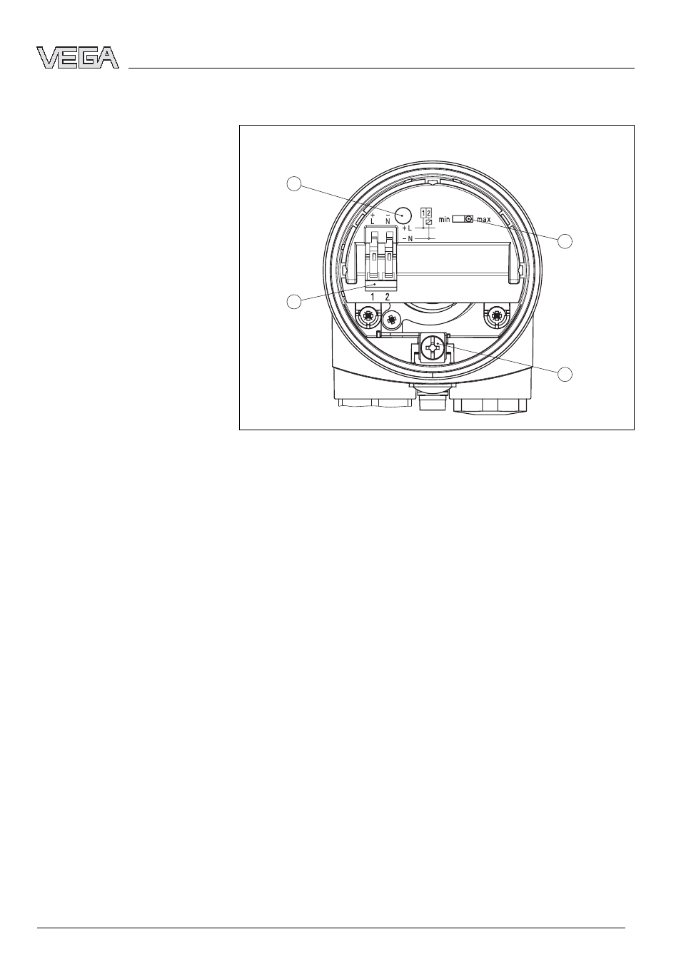
5.3 Wiring plan, single chamber housing
2
3
4
1
Fig. 8: Electronics and connection compartment
1
DIL switch for mode adjustment
2
Ground terminal
3
Screwed terminals
4
Control lamp
We recommend connecting VEGAVIB 55 in such a way that
the switching circuit is open when there is a level signal, line
break or failure (safe condition).
The contactless electronic switch is always shown in non-
operative condition.
The instrument is used for direct control of relays, contactors,
magnet valves, warning lights, horns etc. It must not be
operated without an intermediately connected load, because
the electronics would be destroyed if connected directly to the
mains. It is not suitable for connection to low voltage PLC
inputs.
Domestic current is temporarily lowered below 1 mA after
switching off the load so that contactors, whose holding current
is lower than the constant domestic current of the electronics,
are reliably switched off.
Electronics and connection
compartment
Wiring plan
VEGAVIB 55 - - contactless electronic switch
17
Connecting to voltage supply
29302
-EN
-070109