3 mounting, Bgt 596, Bgt 596 ex.m – VEGA BGT 596-596 Ex.M User Manual
Page 7: Mounting steps
Carrier BGT 596, 596 Ex.M
7
Operating instruction
2.3 Mounting
BGT 596
Except this operating instruction (BA) the BAs
of the installed module cards have to be
observed.
The mounting of the module cards must start
directly after the blind cover mounted on the left
(4 TE = air gap to the side wall of the carrier of
≥
10 mm).
BGT 596 Ex.M
The instructions and mounting steps described
in the following are part of the explosion protec-
tion and must be maintained exactly.
- Ex-module cards must only be operated via
Ex-modules in the carrier.
- The intrinsically safe circuits can be sepa-
rated by means of the supplied separating
chambers.
- The protection IP 20 requested for Ex-appli-
cations must be ensured by a total equip-
ment (module cards and/or blind covers).
- The following installation regulations must be
observed for mixed load.
Examples:
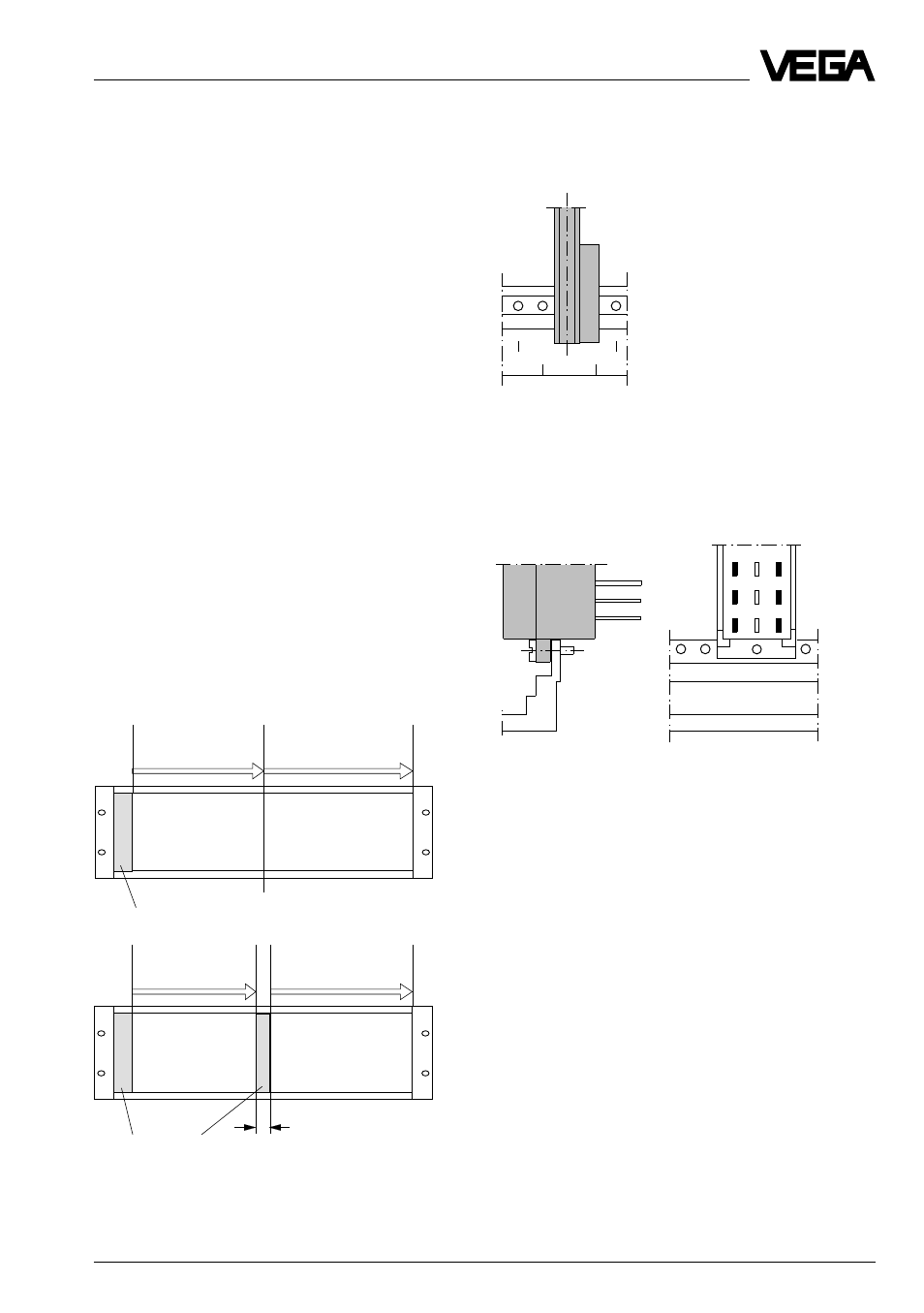
Mounting steps
Step 1
Snap-in the guide rails into the respective
module of the carrier (e.g. module position 5).
Step 2
VEGA-Ex-module
cards
VEGA-not-Ex- and/ or
module cards of other
manufacturers
Blind cover
No distance conditions
VEGA-Ex-module
cards
VEGA-not-Ex- and/
or module cards of
other manufactur-
ers
Blind cover
Distance
≥
6 mm
(min. 2 TE)
3
5
7
06
03
o 31 o
o 29 o
o 27 o
Mount the multipoint connector from the inner
side of the carrier to the rear board.
The max. voltage on the circuits must not exceed
250 V
eff
.