VEGA 145 Safety barrier User Manual
Page 5
Technical Information
Type 145
5
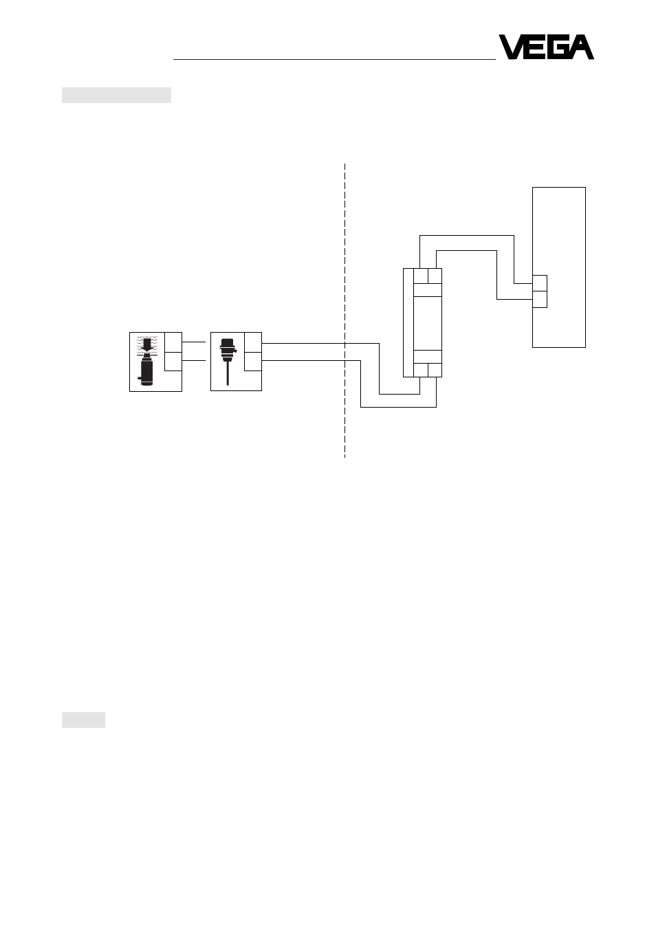
Electrical connection
+
-
11 12
1
2
+ -
+ -
1
2
1
2
Wiring diagram
Input
The non-intrinsically safe input of the safety barrier
(terminal 11 / 12) can be connected with standard
cable to the signal conditioning instrument.
Screened cable is recommended if electromagnetic
fields have to be expected.
Attention:
The screen should be single-ended.
Attention:
The connections of safety barrier (input / output)
should under no circumstances be exchanged.
Output
The wiring of the intrinsically safe output of the
safety barrier (terminal 1 / 2) with the transducer (in
hazardous area must be carried out according to
the local codes of practice and with reference to
the certificates of conformity supplied with the
barrier.
Set-up
• Carry out electrical connection acc. to the wiring
diagram.
• Carry out adjustment (with connected safety
barrier).
• For further details see the technical data sheet
of the connected sensor or signal conditioning
instrument.
hazardous area
hydrostatic
sensor with
oscillator
capacitive
electrode with
oscillator
intrinsically
safe circuit
VEGA
safety barrier
Type 145
non-Ex-approved
signal conditoning
instrument mains
supply
≤
250 V
non-hazardous area
non-intrinsically safe