3electrical connection 4 technical data – VEGA VEGACONNECT User Manual
Page 3
VEGACONNECT
3
Technical Information
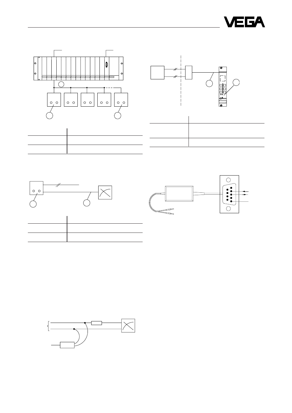
2.3
Sensor in conjunction with VEGALOG 571
1
15
16
sensors
VEGACONNECT
5
4
3
2
1
9
8
7
6
VBUS
2 mm-plug
RS 232
D-Sub-plug
9-pole
GND
RxD
TxD
146
1
2
Sensor
Ex-area
not-Ex-area
e.g. VEGAMET 514 V
CONNECT-
sockets in the
front plate
connection
line
2.5
Ex-sensors with VEGAMET 509 V, 512 V,
514 V or VEGAMET 515 V
Connection points
Parameter adjustment
1
VEGAMET
Sensor
2
Sensor
3
Electrical connection
4
Technical data
Power supply
from PC/LAPTOP via
RS 232
Power consumption
max. 8 mA
Voltage
max. 15 V
Transmission rate
9.600 baud
Data format
8 bit (ASCII-Code)
Parity
even
Start / Stop
1 bit each
Galvanic separation
between VBUS and RS 232
Line length
RS 232 approx. 30 cm
VBUS approx. 150 cm
Permissible
ambient temperature
-20
°
C … +60
°
C
Storage and
transport temperature
-20
°
C … +70
°
C
Housing material
shock-resistant Polystyrol
upper part light grey
lower part agate
Housing dimensions
W x H x D
= approx. 100 x 52 x 30 mm
Weight
- with connection line
approx. 200 g
connection line
CONNECT
CONNECT
CONNECT
CONNECT
CONNECT
Connection points
Parameter adjustment
1 … 15
respective sensor
16
Sensor 1 … 15
2.4
Compact and dust Ex-sensors
2
1
Sensor
Power supply
connection line to
indicator
CONNECT
Connection points
Parameter adjustment
1
Sensor
2
Sensor
Note
A digital signal (VBUS) is additionally modulated to the
0/4 … 20 mA-output. Acc. to the connected output (e.g.
indicator) this signal is damped by the internal resistor of
the output, if it is smaller than 100
Ω
. For analog inputs of
PLC-systems this resistor is generally
≥
100
Ω
, so that no
damping is caused. In case of a low impedance indicator a
load resistor of R = 100
Ω
must be connected in the
0/4 … 20 mA-line and VEGACONNECT must be
connected to this resistor.
CONNECT-sockets on
the sensor
CONNECT-sockets on
the sensor
EV-card
CPU-card
to sensor
+
-
R = 100
Ω
VEGACONNECT