All unit in-and outputs are electrically separated – Velleman LAB2 User Manual
Page 3
3
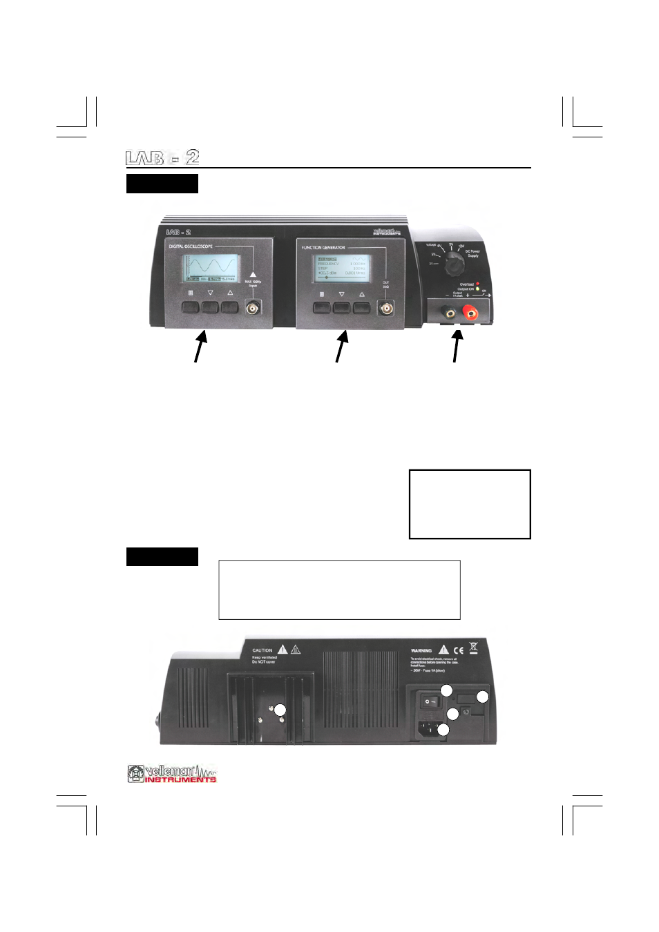
Survey of the front & rear panel
1.
Mains connector (check if unit complies with your local AC voltage)
Unit power supply: 115 or 230Vac / 20VA (check unit back side !)
2. Main power switch.
3. Main Fuse
4. AC power label
5. Power supply heatsink, caution this part can get hot.
BACK SIDE
OSCILLOSCOPE
bandwidth: up to 10 MHz (-3dB*)
input range:
1mV to 20V/division in 14 steps
input coupling: DC, AC and GND
Real time sample rate up to 40MS/s
AD resolution: 8 bits
time base: 250ns to 1h per division
auto set-up function
probe x10 readout option
readouts: DC, AC+DC,True RMS, dBm,
Vpp, Min-Max. (±2.5%)
audio power calculation in 2 to 32 ohms
Maximum input. 100Vp AC+DC
Probe: 1M ohms 60MHz x1 - x10
White LED backlight
* -4dB at: 1mV, 2mV, 5mV, 0.1V and 2mV
FUNCTION GENERATOR
DDS type generator (Direct Digital
Synthesis)
DAC resolution: 10 bits
frequency range: from 1Hz to
1.000.000Hz (± 0.01%)
frequency steps: 1Hz, 10Hz, 100Hz, 1kHz
and 10kHz
waveforms: sine, square and triangle
sweep function with bi-direction option
output voltage: max. 15Vpp
real output level measurement:
dBm / Vrms or Vpp readout (±3%)
typical sine wave distortion (THD):
< 0.1% @ 0dB / 600 ohms
square wave rise/fall time: typ. 0.2µs
output impedance: 50 ohms
multi-language menu (UK/FR/NL/DE/ES)
White LED backlight
POWER SUPPLY
voltage output (fixed voltages):
3V, 5V, 6V, 9V, 12V ( ±5% )
peak output current: 1A
LED Output overload indicator
LED Output ON indicator
output ON/OFF switch (at the side)
FRONT SIDE
All unit in-and
outputs are
electrically
separated.
5
2
1
4
3