Bosch GOP 10,8 V-LI Professional User Manual
Page 16
16 | English
1 609 92A 009 | (7.1.13)
Bosch Power Tools
The battery is equipped with a NTC temperature control
which allows charging only within a temperature range of be-
tween 0 °C and 45 °C. A long battery service life is achieved
in this manner.
Removing the battery
To remove the battery
2, press the unlocking buttons 1 and
pull the battery out of the machine to the rear.
Do not exert
any force.
Battery Charge-control Indication
The three green LEDs of the battery charge-control indicator
4 indicate the charge condition of the battery 2. For safety
reasons, it is only possible to check the status of the charge
condition when the machine is at a standstill.
To indicate the charge condition, press and hold button
3 of
the switched off machine.
Changing the Tool
Before any work on the machine itself (e. g. mainte-
nance, tool change, etc.) as well as during transport
and storage, remove the battery from the power tool.
There is danger of injury when unintentionally actuating
the On/Off switch.
Wear protective gloves when changing application
tools/accessories. Contact with the application tool/ac-
cessoriy can lead to injuries.
Selecting the Application Tool/Accessory
Mounting/Replacing the Application Tool/Accessory
If required, remove an already mounted application tool/ac-
cessory.
For removing the application tool/accessory, loosen the
screw
11 with the Allen key 12 and remove the application
tool/accessory.
Mount the requested application tool/accessory (e.g. plunge
cut saw blade
10) in such a manner on the tool holder 8 that
the offset faces downward (see illustration on the graphics
page; marking on the application tool/accessory is readable
from above).
Turn the application tool/accessory to a position favourable
for the respective job, and allow it to engage into the cams of
the tool holder
8. 12 different positions are possible, each
offset by 30°.
For more intermediate positions, the adapter
13 (accessory)
can be used: Allow the adapter to engage with the smooth
side onto the cams of the tool holder
8 (see illustration on the
graphics page). Position the application tool/accessory onto
the adapter in any position.
Fasten the application tool/accessory with bolt
11. Tighten
the bolt with Allen key
12 until the spring washer of the bolt
faces flush against the application tool/accessory.
Check the tight seating of the application tool/accesso-
ry. Incorrect or not securely fastened application tools/ac-
cessories can come loose during operation and pose a haz-
ard.
Mounting/Replacing a Sanding Sheet on the Sanding
Plate
The sanding plate
14 is fitted with Velcro backing for quick
and easy fastening of sanding sheets with Velcro adhesion.
LED
Capacity
Continuous lighting 3 x green
2/3
Continuous lighting 2 x green
1/3
Continuous lighting 1 x green
<1/3
Flashing light 1 x green
Reserve
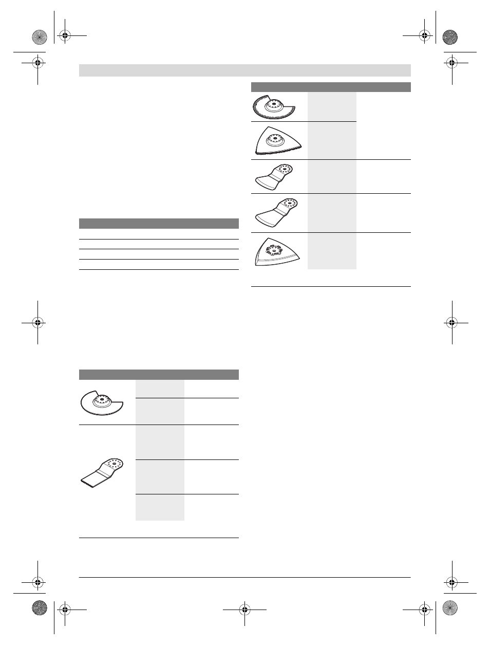
Accessory
Material
HCS wood seg-
ment saw blade*
Wooden materials,
plastic
BIM segment saw
blade*
Wooden materials,
plastic, non-ferrous
metals
HCS plunge cut
saw blades,
wood*
Wooden materials,
plastic, gypsum
and other soft ma-
terials
BIM plunge cut
saw blades,
metal*
Metal (e. g. unhard-
ened nails, screws,
smaller profiles),
non-ferrous metals
BIM plunge cut
saw blade, wood
and metal*
Wood, metal, non-
ferrous metals
* Optional accessory; for the complete accessories please see Bosch
accessory programme.
HM-Riff segment
saw blade*
Grouting joints,
soft wall tiles,
glass-fibre reinforc-
es plastic and other
abrasive materials
HM-Riff delta
plate*
Scraper, rigid*
Carpets, coverings
Scraper, flexible* Silicone and other
elastic materials
Base plate for
sanding, series
Delta 93 mm*
Depends on sand-
ing sheet
Accessory
Material
* Optional accessory; for the complete accessories please see Bosch
accessory programme.
OBJ_BUCH-630-007.book Page 16 Monday, January 7, 2013 10:59 AM