English – ASRock H81M-GL User Manual
Page 26
24
English
ATX Power Connector
(24-pin ATXPWR1)
(see p.1, No. 6)
This motherboard pro-
vides a 24-pin ATX power
connector. To use a 20-pin
ATX power supply, please
plug it along Pin 1 and Pin
13.
ATX 12V Power
Connector
(8-pin ATX12V1)
(see p.1, No. 4)
This motherboard pro-
vides an 8-pin ATX 12V
power connector. To use a
4-pin ATX power supply,
please plug it along Pin 1
and Pin 5.
Infrared Module Header
(5-pin IR1)
(see p.1, No. 17)
This header supports an optional
wireless transmitting and
receiving infrared module.
Chassis Intrusion Header
(2-pin CI1)
(see p.1, No. 16)
This motherboard
supports CASE OPEN
detection feature that
detects if the chassis cove
has been removed. This
feature requires a chassis
with chassis intrusion
detection design.
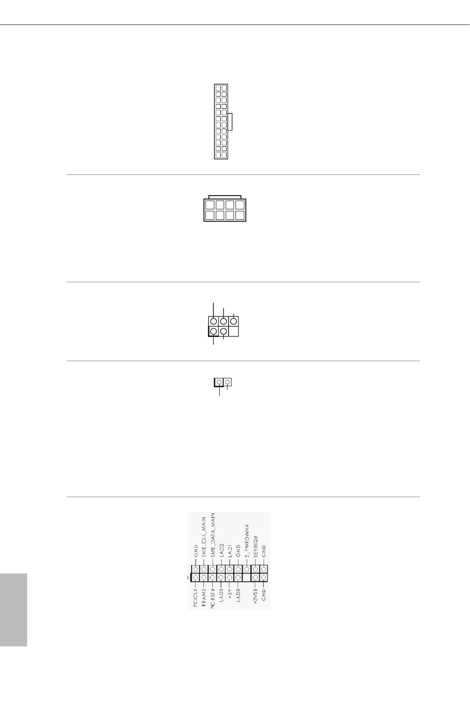
TPM Header
(17-pin TPMS1)
(see p.1, No. 18)
This connector supports
Trusted Platform Module
(TPM) system, which can
securely store keys, digital
certificates, passwords,
and data. A TPM system
also helps enhance
network security, protects
digital identities, and
ensures platform integrity.
12
1
24
13
GND
IRRX
DUMMY
+5VSB
IRTX
1
1
Signal
GND
4 1
8 5