English – ASRock FM2A75M-DGS R2.0 User Manual
Page 11
11
ASRock FM2A75M-DGS R2.0 Motherboard
English
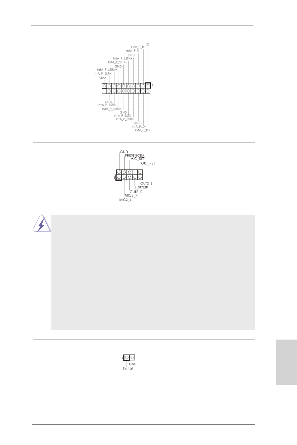
Front Panel Audio Header
This is an interface for the front
(9-pin HD_AUDIO1)
panel audio cable that allows
(see p. 2, No. 23)
convenient connection and
control of audio devices.
1. High Definition Audio supports Jack Sensing, but the panel wire on
the chassis must support HDA to function correctly. Please follow the
instruction in our manual and chassis manual to install your system.
2. If you use AC’97 audio panel, please install it to the front panel audio
header as below:
A. Connect Mic_IN (MIC) to MIC2_L.
B. Connect Audio_R (RIN) to OUT2_R and Audio_L (LIN) to OUT2_L.
C. Connect Ground (GND) to Ground (GND).
D. MIC_RET and OUT_RET are for HD audio panel only. You don’t
need to connect them for AC’97 audio panel.
E. To activate the front mic.
For Windows
®
8 / 8 64-bit / 7 / 7 64-bit / Vista
TM
/ Vista
TM
64-bit OS:
Go to the "FrontMic" Tab in the Realtek Control panel. Adjust
“Recording Volume”.
USB 3.0 Header
Besides two default USB 3.0
(19-pin USB3_2_3)
ports on the I/O panel, there is
(see p. 2, No. 21)
one USB 3.0 header on this
motherboard. This USB 3.0
header can support two USB 3.0
ports.
Chassis Intrusion Header
This motherboard supports
(2-pin CI1)
CASE OPEN detection feature
(see p.2, No. 28)
that detects if the chassis cover
has been removed. This feature
requires a chassis with chassis
intrusion detection design.