Section 3 - remote control system, Section 4 - urp-102 point pad – ACR&Artex RCL-300A User Manual
Page 6
Y1-03-0232G
5
Self Park Feature
The RCL-300A has a Self-Park feature. The Self Park function will
automatically return the light to a specific position when turned off.
When mounting the light, determine in advance the direction that the
light should face when it is turned off. Align the red marker on the base
180
° opposite of the final facing direction.
To activate the Self-
Park feature, press the “Speed” button on the URP-
102 Point Pad™ for more than five (5) seconds.
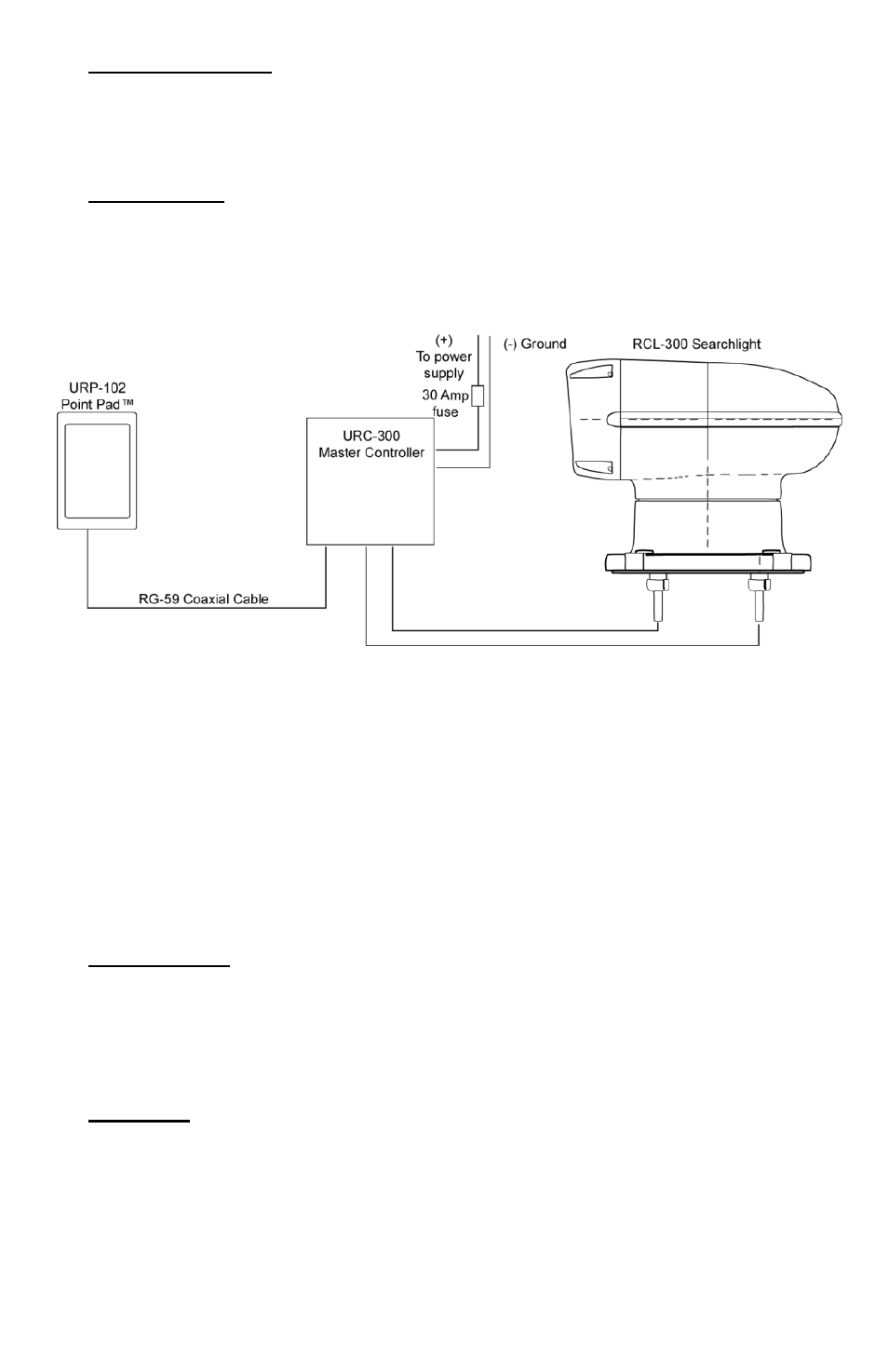
Figure 2- URC-300 Master Controller unit (mounted upright)
Single Point Pad connection configuration
SECTION 3 - REMOTE CONTROL SYSTEM
The Remote Control System consists of the URC-300 Master Controller
and the URP-102 Point Pad
™. This system is compatible with 12 VDC
through 24 VDC systems without modification.
SECTION 4 - URP-102 POINT
PAD™
Case options
The URP-102 Point Pad
™ is supplied as a surface mount unit (see
Figure 3). A flush mount option is provided. To switch mounting options,
unscrew the six (6) screws on the unit’s back plate and remove the front
cover. Fit the Point Pad
™ with the flush mount cover, replace the back
plate and screw the unit back together.
Mounting
Both the surface mount and the flush mount options require access to
the backside of the mounting location. Verify that there are not any
obstructions behind the area where the switch is to be located, e.g.,
bulkheads, wires, plumbing or hardware. Check that the coax cable from
the Master Controller can be routed to this location. Generally, the Point
Pad™ should be mounted in a protected area.