Rmq 9190, 2 > qd alarm connection & operation – Acnodes RMQ 9190 User Manual
Page 14
14628 Central Ave,
Chino, CA 91710
tel:909.597.7588, fax:909.597.1939
© Copyright 2013 Acnodes, Inc.
All rights reserved. Product description and product specifications
are subject to change without notice. For latest product information,
please visit Acnodes’ web site at .
RMQ 9190
9U 19” 1280x1024 Rackmount CCTV Monitor
A larm
< 4.2 > QD ALARM Connection & Operation
3 Sensor Activated Alarm
The u nit is equipped with 4 alarm sensor inputs. If any alarm is activated:
¦
the built-in buzzer and the alarm output control relay contact will be activated.
¦
the quad will switch the corresponding channel indicator LED to blinking mode.
¦
a warn ing message depending on different models will be displayed as follows:
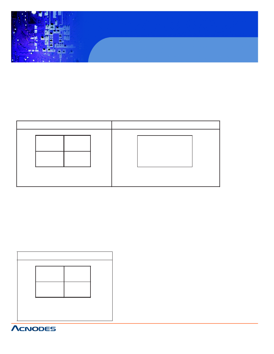
Quad output channel (#4)
LIVE output channel (#5)
Blinking A larm & Title m essage on the
activated c han nel in quad screen
A larm
Full screen display of the activated channel.
A lso display a blinking A larm m essage
Above mentioned alarm can be cleared by any of th e following: 1. Connecting the Alarm Reset In contact, p in #5, of the
female type 9 pin D-sub connector (#8) to G ND. 2. The Alarm Duration time elapses. 3. If the device is operated under
Security Lock ON mode, Push Lo ck button for 2 seconds to disable the function then push any button in the front panel.
4 Video Loss Alarm
L oss of video at any input is automatically detected by the device. The device will:
¦
A ctivate the built-in buzzer.
¦
S witch the correspondin g channel indicato r LED to blinking m ode.
¦
Display warnin g me ssage on quad screen:
Quad output channel (#4)
Video loss
B linking V ideo Loss & Title m es sage
on the activate d channel in quad
screen
¦
The warning message and the buzzer can be cleared
by pushing Lock button (#2) for more than 4 seconds if the
device is operated under Security lock On mode, or pushing
any button on the front panel if the device is operated under
Security lock OFF mode.