Operation guide, Rear panel view, Color – Acclaim Lighting ART 4 User Manual
Page 5
5. Color
To enable Color Menu, hold on pressing the "C" key for about 1s, the key clicks
and the indicator lights up. Then rotate the touch toggle to adjust the RGB
value until you get the desired color.
Up to 4 colors can be recorded in manual mode. Each figure key corresponds to
one color. The procedure to record a color is described below:
Touch "C" key to enable Manual Mode, the key clicks and the indicator is lit.
Repeat step a~d to save more colors to the other 3 figure keys.
All indicators flash momentarily once to indicate the current parameters,
including the value of color and brightness, have been saved into the key.
Touch any of the figure keys to which you wish to record the color, and hold
on for more than 2 seconds.
c.
a.
Rotate the touch toggle to adjust RGB value until you get desired color.
b.
d.
e.
Touch "C" key to enable Manual Mode. Then touch the corresponding button of
1~4 to raise the color which you've stored in the key. The LED indicator lights
up and it starts to display the recorded color.
5.1 Recording Color
5.2 Playback Color
5.3 Setting Fadetime for Color Exchange
Touch "C" key and hold on for 5 seconds till all LED indicators flash once.
Then release the key and the "C" key flashes repeatedly.
Different keys represent different fadetime. The table2 details the fadetime
information.
The existing mode ends and changes to normal mode automatically.
All indicators flash momentarily once to confirm the setting.
Touch any one of these keys--1, 2, 3, 4, P, C, B or S.
To set the fadetime for color exchange, you take the following procedures:
Keys
Fadetime
1
2
3
4
1s
2s
3s
4s
P/C/B/S
0s (no fade time)
Operation Guide
Table 2
Page 6
ART-4 User Instruction
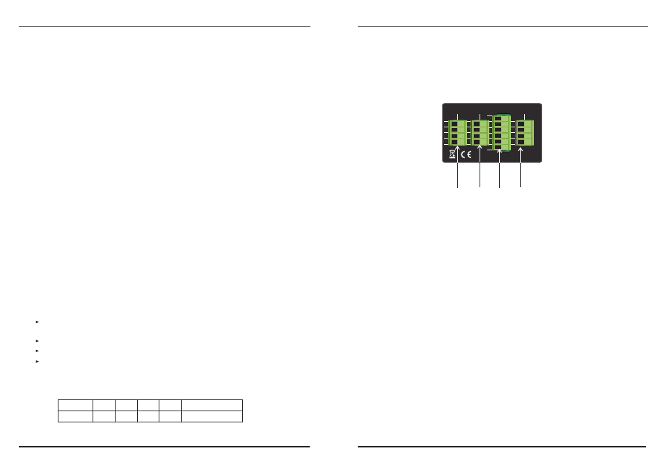
ART-4 features one group DMX OUT with 4-pin terminal connector, one group
POWER IN & PWM OUT with 6-pin terminal connector
The configuration of the terminal is as the following(figure
2):
, a Link In and Link Out
for online operation.
Page 3
ART-4 User Instruction
Rear Panel View
Figure 2
1. LINK IN: 4-pin terminal
2. DMX OUT: 4-pin terminal
3. PWM OUT & POWER IN: 6-pin terminal
4. LINK OUT: 4-pin terminal
LINK IN
DMX OUT
LINK OUT
DC IN
PWM OUT
RoHS
Made in P.R.C.
24-005-1396-01
GND
D-
D+
V+
GND
D-
D+
V+
GND
D-
D+
B
V+
G
R
GND
V in+
V+
1
2
3
4