English – Makita LS1040F User Manual
Page 9
9
ENGLISH
Explanation of general view
1
Base
2
Hex bolt
3
Auxiliary plate
4
Nut
5
Bolt
6
Center cover
7
Socket wrench
8
Shaft lock
9
Loosen
10
Arrow
11
Blade case
12
Arrow
13
Saw blade
14
Spindle
15
Flange
16
Ring
17
Flange
18
Hex bolt
19
Tighten
20
Safety cover
21
Dust spout
22
Dust bag
23
Fastener
24
Lock-off button
25
Switch trigger
26
Lever
27
Turn base
28
Kerf board
29
Sub-fence
30
Adjusting bolt
31
Pointer
32
Miter scale
33
Latch spring
34
Grip
35
Lever
36
Bevel scale
37
Pointer
38
Vise rod
39
Screws
40
Guide fence
41
Vise arm
42
Clamp screw
43
Support
44
Knob
45
Projection
46
Holder
47
Screw
48
Holder assembly
49
Screw
50
Rod 12
51
Cutting line
52
Groove
53
Vise
54
Spacer block
55
Aluminum extrusion
56
Spacer block
57
Over 10 mm
58
Over 460 mm
59
Hole
60
Set plate
61
Screw
62
Triangular rule
63
Hex bolts
64
Arm
65
Hex bolt (A)
66
Top surface of turn base
67
Arm holder
68
Hex bolt (B)
69
Limit mark
70
Screwdriver
71
Brush holder cap
SPECIFICATIONS
Model
LS1040
Blade diameter .................................................................................................................................. 255 mm — 260 mm
Hole (arbor) diameter
For all countries other than European countries ........................................................................... 25.4 mm and 25 mm
For European countries ......................................................................................................................................30 mm
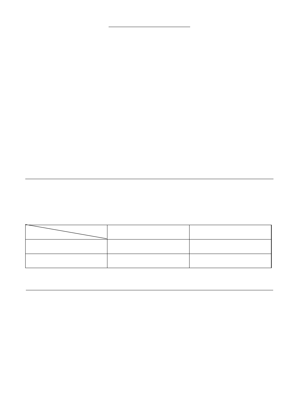
Max. cutting capacities (H x W) with blade 260 mm in diameter
No load speed (RPM) ............................................................................................................................................. 4,600
Dimensions (L x W x H) .....................................................................................................530 mm x 476 mm x 532 mm
Net weight ............................................................................................................................................................... 11 kg
• Due to our continuing program of research and devel-
opment, the specifications herein are subject to change
without notice.
• Note: Specifications may differ from country to country.
Intended use
The tool is intended for accurate straight and miter cut-
ting in wood. With appropriate saw blades, aluminum can
also be sawed.
Power supply
The tool should be connected only to a power supply of
the same voltage as indicated on the nameplate, and can
only be operated on single-phase AC supply. They are
double-insulated in accordance with European Standard
and can, therefore, also be used from sockets without
earth wire.
For public low-voltage distribution systems of
between 220 V and 250 V
Switching operations of electric apparatus cause voltage
fluctuations. The operation of this device under unfavor-
able mains conditions can have adverse effects to the
operation of other equipment. With a mains impedance
equal or less than 0.30 Ohms it can be presumed that
there will be no negative effects. The mains socket used
for this device must be protected with a fuse or protective
circuit breaker having slow tripping characteristics.
Miter angle
Bevel angle
0°
45° (left and right)
0°
93 mm x 95 mm
69 mm x 135 mm
93 mm x 67 mm
69 mm x 95 mm
45° (left)
53 mm x 95 mm
35 mm x 135 mm
49 mm x 67 mm
35 mm x 94 mm