Festool PDC 18 User Manual
Page 14
14
PDC 18/4
GB
6.4
Light and battery capacity indicator
The LED on the lamp [1-2] is both a light and
a battery capacity indicator .
X
Press the LED light switch [1-1]:
1x ... LED, working area illumination
2x ... capacity indicator, indicates the charging
state of the battery pack (not with NiCd and
NiMH battery packs)
7
Settings
7.1
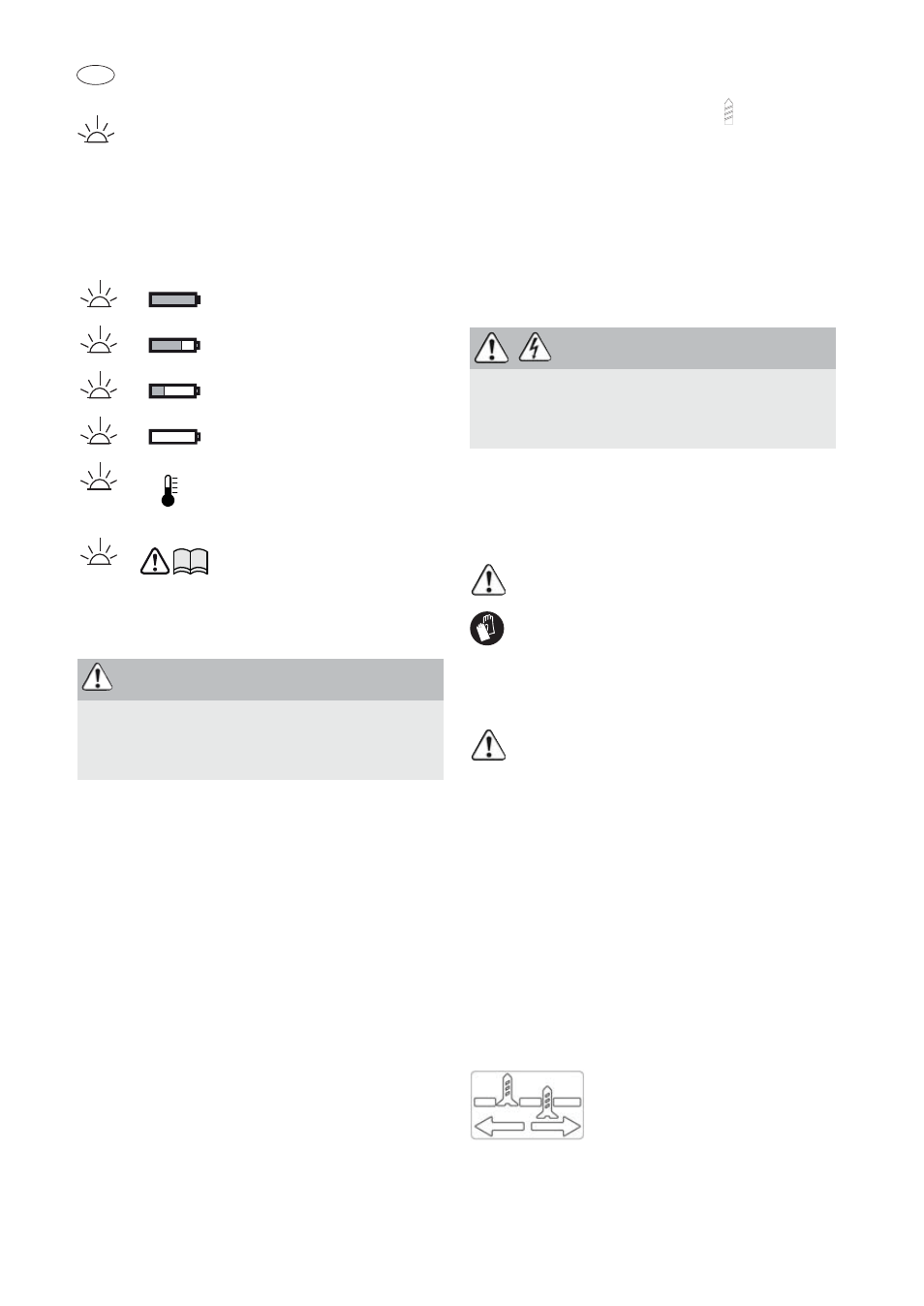
Changing direction of rotation [1-9]
• Switch to the left = clockwise rotation
• Switch to the right = counterclockwise rotation
7.2
Changing gear
You can change gear using the gear switch [1-7].
7.3
Adjusting the torque[1-8]
Fastening
Select the correct torque setting:
Position 1 = low torque
Position 12 = high torque
An acoustic signal sounds when the preset torque
is reached and the machine then switches off. You
must release and press the ON/OFF switch [1-4]
again to start the machine.
Drilling
Mark is aligned with drill symbol
= maximum
torque.
7.4
Impact drilling
L The machine was designed for impact drilling
into tiles, masonry and stone.
Set the selector switch [1-6] to the hammer sym-
bol. Set the adjusting wheel [1-8] to the drill sym-
bol.
8
Tool holder, attachments
L Prior to initial use: apply multi-purpose grease
to the drill spindle and gearbox neck.
8.1
CENTROTEC tool chuck [6]
Quick change of tools with CENTROTEC shaft
Only clamp CENTROTEC tools in CENTRO-
TEC tool chucks.
Wear gloves when replacing!
8.2
Chuck [7]
For clamping drill bits and bits with max. shaft di-
ameter of 13 mm.
Clamp tool centrally in the chuck.
8.3
Angle attachment [8]
Drilling and screwdriving at right angle to machine
(partly as an accessory).
8.4
Tool holder in the drill spindle [9]
Bits can be inserted directly into the hexagon sock-
et holder of the drill spindle.
8.5
Depth stop [10]
The depth stop (partly as an accessory) allows the
user to insert screws to a predefined depth. You can
set the dimension by which the screw head pro-
trudes above or is recessed below the surface of the
workpiece.
Depth setting
Turn the housing [10-1] to set
the desired fastening depth.
Each detent position changes the
fastening depth by 0.1 mm.
Sleeve A/B must be removed before a screw can be
unscrewed.
LED green – lit continuously:
charged > 60 %
LED green – flashing slowly:
charged 30 % – 60 %
LED green – flashing quickly:
charged 0 % – 30 %
LED yellow – lit continuously:
battery is empty
LED red – lit continuously: bat-
tery temperature is outside the
permitted range.
LED red – flashing: indicates a
general fault, e.g. incomplete
contact, short circuit, battery
pack faulty, etc.
WARNING
Risk of injury
X
Always switch off the machine before adjusting
settings!
WARNING
Risk of injury, electric shock
X
Always disconnect the battery pack before any
type of work on the machine!