Front panel and rear panel illustration, Front panel, Rear panel – 888 Digital High Definition Digital Set Top Box HD4000 User Manual
Page 6
4
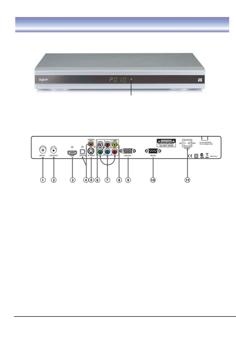
Front panel and rear panel illustration
Front Panel
①
① Green Light To indicate the Stand-by mode ON/OFF (this mode is controlled
by remote control only).
Rear Panel
① ANT IN connect the antenna here.
② LOOP OUT To connect a RF signal from the STB to either the RF Input jack
(antenna) on your VCR or to the antenna input of your TV.
③ HDMI video output used to connect to your HDMI device.
④ PDIF/COAXIAL Digital audio output.
⑤ S-VIDEO Y/C output for a S-VHS or Hi-Fi Video Recorder.
⑥ AUDIOL/R Audio output to connect to your TV.
⑦ YPbPr High definition video output to connect to your TV.
⑧ VIDEO CVBS output to connect to your TV.
⑨ VGA Video output to connect a VGA display monitor.
⑩ RS-232 Serial port for software upgrade.
⑪ POWER Switch ON/OFF.