Set up – Zenoah LRTZ2610 User Manual
Page 8
GB-8
SRTZ2610/SRTZ2610F/LRTZ2610
MIN
SP
ACING
About 19 inches (48 cm)
clamp
arrow mark
(1)
6. Set up
MOUNTING ENGINE
1. Push the shaft tube toward the clutch housing and move
it by hand to check that the drive shaft is engaged with
the gears.
2. Insert the shaft tube into the clutch housing until it bot-
toms, and align the positioning holes on the clutch hous-
ing and the shaft tube and install the screw. When diffi-
cult to engage, twist the engine slightly.
3. Fasten the clamp securely with two screws.
WARNING
Never use any screws other than those specified by the
manufacturer, or the engine can get loose, resulting in a
hazardous event.
IMPORTANT
Tighten the screws gradually by turns.
CONNECTING THROTTLE WIRE
1. Remove the air cleaner cover.
2. Connect the end of the throttle wire to the joint on the top
of the carburetor.
1. Connect throttle wire with carburetor. Insert the cable to
the end of adjuster fix the throttle cable by tightening M3
screw. (Tightening torque: 0.4 ~ 0.8 N.m.)
2. Make sure the ‘STOPPER-PLATE’ of carburetor moves to
contact with ‘IDLING ADJUST SCREW’ and the ‘SWING-
ARM’ of carburetor moves to contact with ‘FULL ON
STOPPER’ by gripping throttle lever.
CONNECTING SWITCH WIRES
• Connect the switch wires between the engine and the
main unit. Pair the wires of the same color.
CLAMP
NOTE
Be the clamp in the location of the
arrow mark.
INSTALLING HANDLE
NOTE
The handle is put during the arrow mark.
• Mount the handle to
the shaft tube and
clamp it at a location
that is comfortable
to you.
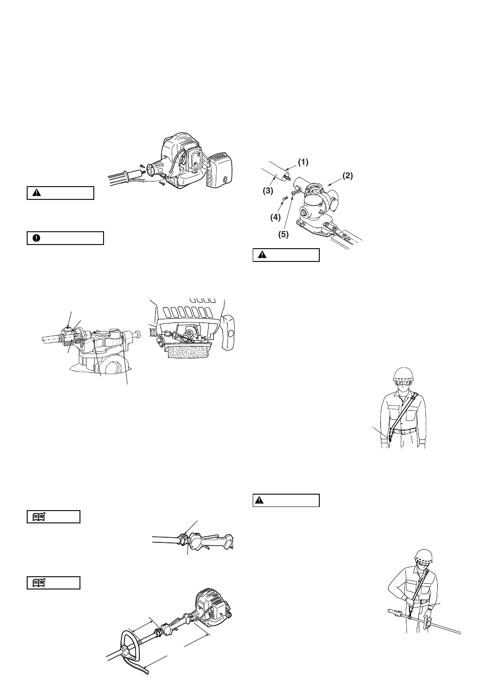
ATTACHING THE TRIMMING MECHANISM
1. Remove the cap on the end of the main pipe.
2. Remove the screw screwed into the end of the trim-
ming mechanism.
3. Insert the end of the trimming mechanism into the main
pipe.
4. Line up the hole on the end of the trimming mecha-
nism into which the screw is to be inserted with the
hole on the main pipe, and screw the screw firmly in.
5. Using a 10-mm wrench, screw in the hexagonal bolt
provided to fix the trimming mechanism into place.
WARNING
ALWAYS WEAR THE PROVIDED HARNESS WHEN
USING THE MACHINE!
Always make sure the machine is hooked securely
to the harness.
If you don't, you will be unable to control the machine
safely. This can result in injury to yourself or others.
Never use a harness with a defective quick release
or any other damage.
HOW TO WEAR
1. Wear the provided harness without twisted bands, with
the hanger on your right side.
QUICK RELEASE
The harness is equipped with a “QUICK RELEASE”devise.
To release the machine from the harness in emergency
situations, please follow the procedure as explained
below.
WARNING
Make sure to check proper working of the QUICK RE-
LEASE device BEFORE operating the machine.
Make sure to hold the unit securely when using the
QUICK RELEASE.
While holding the unit by your
right hand securely, press both
sides of the buckle. sides of
the buckle.
(1) Buckle
BALANCE UNIT
1. Put on strap and attach unit to strap.
2. Depending on the working posture, slide clamp up or
down until unit balances and the strap fits your body.
(1) Main pipe
(2) Trimming
mechanism
(3) Screw hole
(4) Screw
(5) Fastening bolt
(1)
(1) Hanger
Insert the cable
to the end of
adjuster
Full on stopper
Idling adjust screw
M3 screw
Adjuster
Bolt