Attaching the seat, Manual adjustment seat, Quick adjustment seat – Yard Machines 840 Thru 849 User Manual
Page 10: Attaching the deck links (hardware a)
10
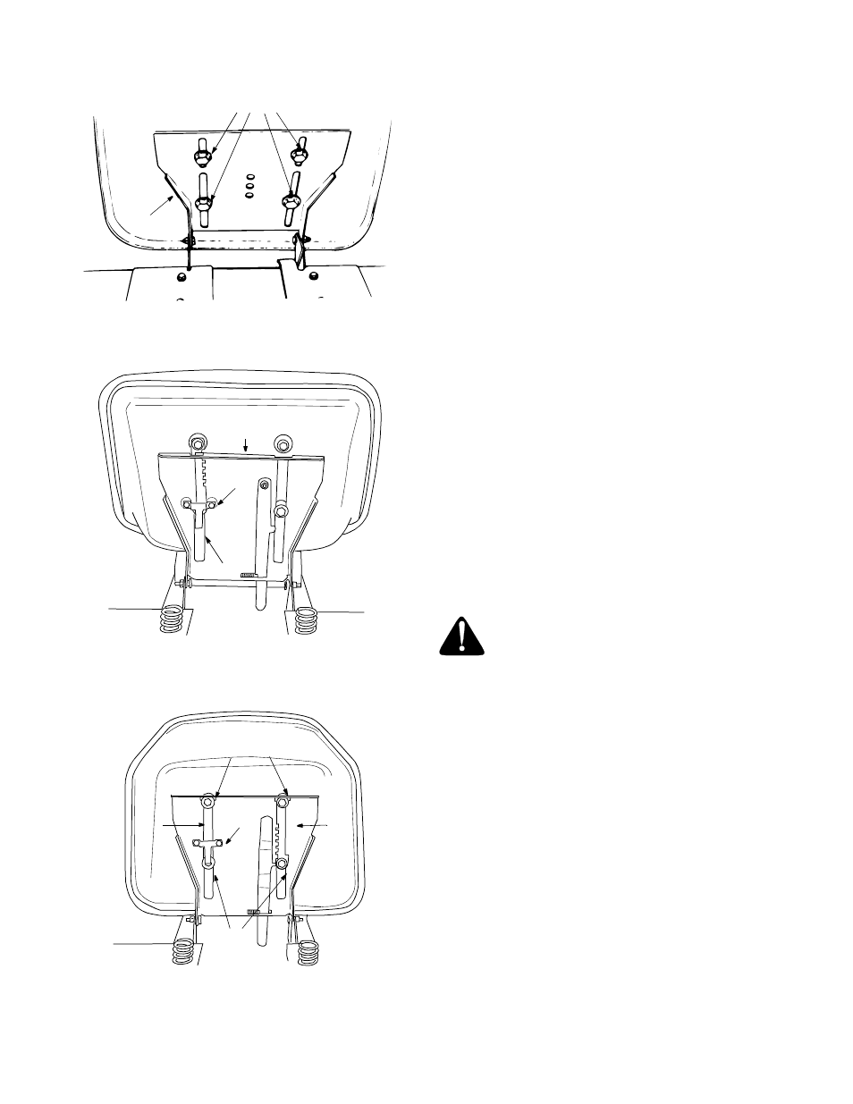
Figure 2
Figure 3
Figure 4
ATTACHING THE SEAT
There are two different seat pivot brackets used on this
series of garden tractor, a manual adjustment seat or a
quick adjustment seat. See Figure 2 and 4 to identify
which seat is on your unit. Follow the instructions which
apply to your garden tractor.
MANUAL ADJUSTMENT SEAT
Remove the four screws which secure the seat to the
seat pivot bracket. Turn the seat around and place in
position against the seat pivot bracket, lining up the
slotted holes in the pivot bracket with the holes in the
seat. Select desired position for the seat, and secure
with the four screws. See Figure 2.
NOTE: Your seat may have been shipped in a box.
Remove the four screws from the bottom of seat and
place seat in position against the seat pivot bracket.
Follow the directions above to attach the seat.
QUICK ADJUSTMENT SEAT
Pull out tab on seat stop and hold open while sliding
seat out of seat pivot bracket. See Figure 3. Turn the
seat around and line up plastic seat spacers with the
slots in seat pivot bracket. Slide seat in until front seat
spacer engages the seat stop. See Figure 4. To adjust
the seat refer to the adjustment section in this manual.
NOTE: If your seat was shipped in a box, line up plastic
seat spacers with the slots in seat pivot bracket and
slide seat in until front seat spacer engages seat stop.
WARNING: Before operating your unit,
stand behind quick adjustment seat and
pull back on seat, making sure seat is
engaged in seat stop.
ATTACHING THE DECK LINKS
(Hardware A)
The three adjustable deck links have been shipped
unassembled. Attach as follows.
•
Start 1/2" hex nuts on eyebolts until nuts are
flushed with ends of eyebolts. See Figure 5.
•
Insert eyebolts and hex nuts into the adjustable lift
links located under the tractor. See Figure 5.
•
Thread eyebolts into the lift links and hex nuts. The
left rear link should be adjusted so the eyebolt
hangs about 3-1/2 inches below the lift link. The two
front links should be adjusted so the eyebolts hang
about 2-1/8 inches below the lift links. See Figure 5.
Screws
Seat
Pivot
Bracket
Manual Adjustment Seat
Quick Adjustment Seat
Seat Pivot
Bracket
Tab
Seat
Stop
Quick Adjustment Seat
Seat
Spacers
Slot
Slot
Seat
Stop
Seat
Spacers