Wind Crest CTI304D User Manual
Page 2
Page 2 of 8 11067.00 Rev B
COOKTOP INSTALLATION
WARNING
– DISCONNECT POWER BEFORE INSTALLING COOKTOP.
FOAM TAPE
– A foam tape is provided to seal the cooktop edges to the countertop. Turn the cooktop upside
down (USE A TOWEL OR TABLE CLOTH BETWEEN COOKTOP AND SUPPORT SURFACE) and apply the
tape to bottom side edges of metal frame. The tape should be approximately 1/16 inch from the edge of the Glass
& Rear Extrusion FIG
– 2.
Fastening Cooktop
– Fasten the two hold down straps with screws supplied see (fig -3). Install the cooktop in the
counter top cutout, Center the cooktop in opening, and secure hold down straps to cabinet side with (2) wood
screws.
ELECTRICAL CONNECTION
Attach flexible conduit, four (4) foot cable, located at center rear of cooktop bottom, to junction box.
Connect cooktop lead wires to junction box supply wires, in proper phase: black to black (L1), red to red (L2),
and green wire to ground. No white wire connection is required. CAUTION: You must shield white power
supply wire if it is installed in the J-Box. This will result in compliance with the National Electrical Code.
Location of Data Plate bottom of cooktop. See FIG – 2.
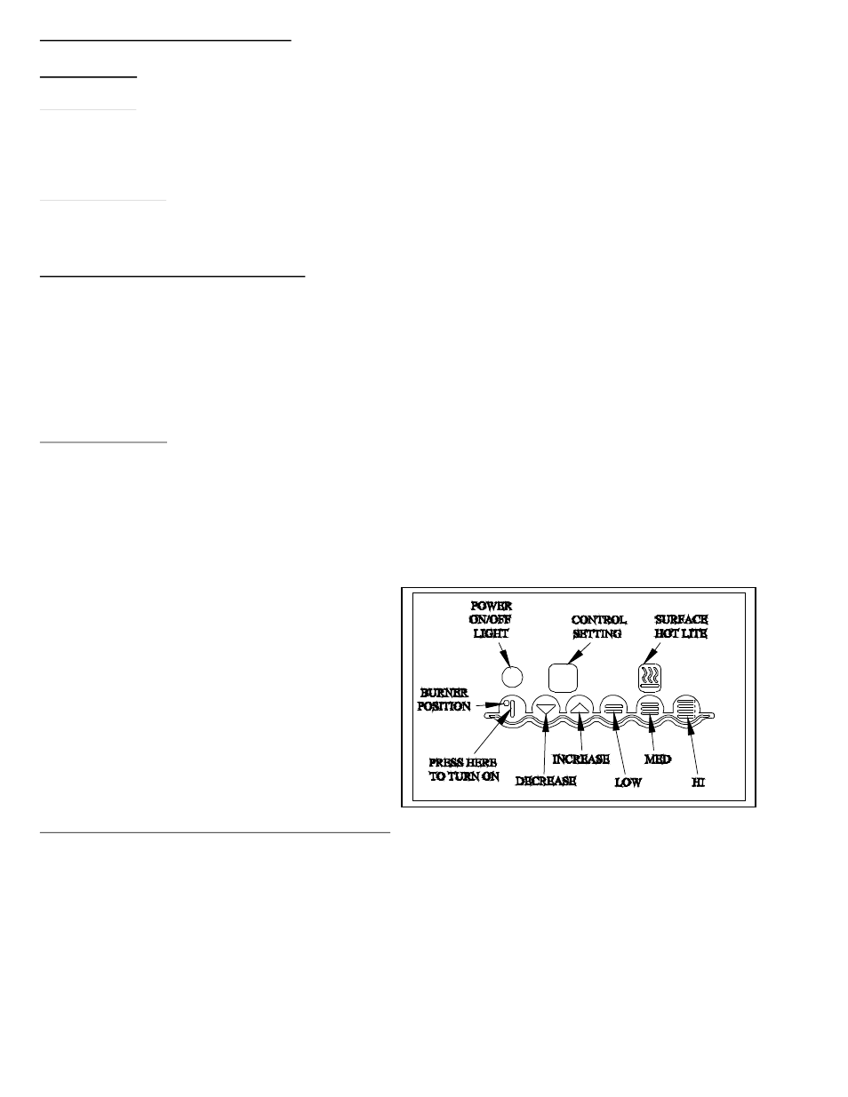
START UP TEST
Remove all items from cooktop
Clean cooktop with Windex or clean damp cloth.
Turn power on at service panel. The controls will automatically cycle on and then turn off.
Turn Element on to check unit operation. Note: You must use a pot that attracts a magnet on pan bottom to
test operation. Put a small amount of water in pot to
prevent damaging the pot.
Press HI, then MED and LOW
Increase setting then Decrease
Turn controls off after checking operation.
CABINET PREPARATION AND CLEARANCE
– Be sure your appliance is properly installed and grounded
by a qualified technician.
To eliminate the risk of burns or fire by reaching over heated cooking utensils, cabinet storage space located above
the surface units should be avoided. If cabinet storage is to be provided, the risk can be reduced by installing a
range hood that projects horizontally a minimum of 5 inches beyond the bottom of the cabinets.
NOTE: Plan the installation so that the electrical connection is accessible from the front of the cabinet (see FIG-4),
and all of the following minimum dimensions are provided.